
User Manual
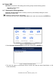
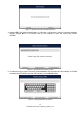
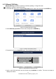
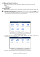
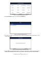
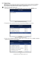
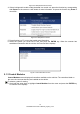
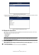
Table Of Contents
- One-Year Limited Warranty
- Safety Information
- 1 Using This Manual
- 2 Introductions
- 3 Getting Started
- 4.Vehicle Identification
- 5 Diagnostic Operations
- 6 Maintenance
- 6.1 Oil Service Reset
- 6.2 Electronic Parking Brake
- 6.3 Battery Replacement (BRT)
- 6.4 Diesel Particulate Filter (DPF) Regeneration
- 6.5 Throttle Body Alignment (TPS/TBA)
- 6.6 Steering Angle Sensor (SAS) Calibration
- 6.7 Continuous Variable Transmission (CVT)
- 6.8 Gear Learning
- 6.9 Tire Pressure Monitoring System Programming
- 6.10 Odometer
- 6.11 Injector Coding
- 7 OBDII/EOBD Operations
- 8 System Setup
- 9 Update

20
NT6X4Elite Series User’s Manual_English_V1.02
Figure 5-6 Sample Control Module Screen
2. Select the system you would like to test. When the scanner has established connection with the
vehicle, the Control Module menu displays.
Figure 5-7 Sample Control Module Menu Screen
5.2 Diagnostic Operations
After a system is selected and the scanner establishes communication with the vehicle, the Function
Menu displays. The menu options may include:
● ECU information
● Read Codes
●
Clear Codes
● Live Data
NOTE
Not all function options listed above are applicable to all vehicles. Available options may vary by the
year, model, and make of the test vehicle.
5.2.1 ECU Information
ECU Information screen displays the identification data of the control module under test, such as the
control module identification string, the control module coding, and Work Shop Code.
To read ECU information:
1. Select ECU Information from the menu and press the ENTER key.