nT-A3800 NanoPC User’s Manual
Trademark: All trademarks are the property of their respective owners. Version: User’s Manual V1.1 for nT-A3800 NanoPC. CA UT IO N Symbol description: ! Caution : refers to important information that can help you to use NanoPC better, and tells you how to avoid problems. WEEE: The use of this symbol indicates that this product may not be treated as household waste.
CA UT IO N Safety Notice : ! Before using this product, please read the below safety notice carefully, this will help to extend the product’s lifecycle, and work normally. ■ When NanoPC is working, please make sure its ventilation system is working. ■ The power adapter is dissipating heat during normal use, please be sure not to cover it and keep it away from your body to prevent discomfort or injury by heat exposure.
Table of Contents Chapter 1 Introducing the NanoPC Top View....................................................................................................2 Front Side View.........................................................................................2 Back Side View.........................................................................................3 Bottom View..............................................................................................
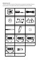
Accessory List Thanks for choosing our products. Please check the accessories listed below. If there is anything broken or lost, please contact with your distributors as soon as possible. DVI to VGA Adapter Power Adapter Power Cord Magnet Rubber Foot Vesa Mount Seatbase Opening Tool Mini PCIe Half Card Support Screw Cover Screw for VESA Mounting (M8.0X9.7mm)(4X) Screw for HDD Support Bracket (M:4.7X2.85mm)(4X) 2.43mm 4.40mm 4.85mm Screw for Half MiniPCIe Half Card Support Bracket (M:4.4X4.
This chapter introduces NanoPC’s outlook : ■ Top View ■ Front Side View ■ Back Side View ■ Bottom View
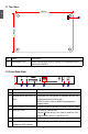
1-1 Top View 1 190mm 1 135mm No. 1 Name Description Kensington Lock Attach a Kensington security system or a compatible lock to secure your NanoPC 1-2 Front Side View 24mm 1 2 3 4 5 6 No. Name Description 1 Headphone Port Connects to a headphone 2 Microphone In and SPDIF In Port Connects to a microphone or playback devices with optical connectors(3.5mm jack) SPDIF function requires additional adapter and adapter cable.
1-3 Back Side View 1 1 2 3 4 5 6 No. Name Description 1 USB 2.0 Ports Connects to USB devices 2 Display Output Port Connects to display device 3 HDMI Port Connects to HDMI audio and video 4 Network Port Standard RJ-45 network port 5 Line Out and SPDIF Out Port Connects to powered analog speakers or recording devices with optical connectors(3.5mm jack) SPDIF function requires additional adapter and adapter cable.
In this chapter, the placement and the connection of some necessary peripherals will be introduced.
2-1 Placement of NanoPC 1. On the Desk 1.1.You can install your NanoPC in the Seatbase like the right image. 2 1.2. If there is enough space on your desk, you can simply put your NanoPC on the tabletop as shown below. 2. On the Display Back This is the best space-saving way. 2.1. Use four screws to fasten the Vesa Mount onto the display back. CA UT IO N ! To install this bracket, your display must follow VESA75/VESA100 standard.
2 2.2. Fit the NanoPC into the Vesa Mount with power button locating at the top for easy touch. 2 CA UT IO N 1 ! Lift up the NanoPC straightly to take it out.
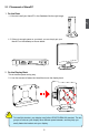
2-2 Connection of NanoPC 1. Connect the Monitor Connect a monitor to the NanoPC through DVI connector. CA UT IO N 2 ! ■ Please use the customized DVI-VGA Adapter that comes with your NanoPC to get a higher resolution on your VGA display. ■ You could have access to display adjustment for some HDTV or HD display connected via HDMI port by using the scaling function in “AMD VISION Engine Center”, a utility, which is available after the installation of AMD Chipset Driver.
3. Connect the Network Cable 2 Connect LAN cable to the RJ-45 port, with the other end connected to a hub or switch. Hub or Switch 4. Connect the Power Cord Connect the power adapter to the power input port of the NanoPC, and push the power but ton to start it. 1 Outlet 3 CA UT IO N 2 ! The power adapter is dissipating heat during normal use, please make sure not to cover it and keep it away from your body to prevent discomfort or injury from heat exposure.
This chapter tells how to change system settings through the BIOS Setup menus. Detailed descriptions of the BIOS parameters are also provided. You have to run the Setup Program when the following cases occur : 1. An error message appears on the screen during the system Power On Self Test (POST) process. 2. You want to change the default Item settings.
Enter BIOS Setup ! We do not suggest that you change the default values in the BIOS Setup, and we shall not be responsible for any damage which resulted from the change you made. 3 CA UT IO N The BIOS is the communication bridge between hardware and software, correctly setting up the BIOS parameters is critical to maintain optimal system performance.
Main The BIOS Setup is accessed by pressing the or button after the Power-On Self-Test (POST) memory test begins and before the operating system boot begins. Once you enter the BIOS Setup Utility, the Main Menu will appear on the screen. The Main Menu provides System Overview information and allows you to set the System Time and Date. Use the “←” and “→” cursor keys to navigate between menu screens. Aptio Setup Utility - Copyright (C) 2012 American Megatrends, Inc.
Advanced Aptio Setup Utility - Copyright (C) 2012 American Megatrends, Inc. Main Advanced Boot Security Save & Exit [AHCI Mode] [Enabled] [Enabled] [Enabled] [Last State] [Disabled] [Auto] Select the SATA Mode Option: (1) IDE Mode (2) AHCI Mode 3 SATA Mode Deep Sleep Support USB 2.0 Port S3 Wakeup LAN / USB 3.0 Port S3 Wakeup Restore on AC Power Loss Supporting C6 power Loss Integrated GPU UMA Frame Buffer → ←: Select Screen ↑ ↓: Select Item Enter: Select +/-: Change Opt.
► Restore on AC Power Loss This item is used to set which state the PC will take with when it resumes after an AC power loss. ► Supporting C6 power Loss This item is used to enable or disable C6 power state,which is featured in Fusion processors. ► Integrated GPU UMA Frame Buffer This item is used to set Integrate Graphics UMA Frame Buffer Size.
Boot Aptio Setup Utility - Copyright (C) 2012 American Megatrends, Inc. Main Advanced Boot Boot Security Save & Exit Boot Configuration Bootup Numlock State Quiet Boot Fast Boot Lanch CSM Lanch LAN OpROM policy Built-in EFI Shell Support Select the keyboard Numlock state [On] [Disabled] [Enabled] [Enabled] [Do not launch] [Disabled] 3 Boot Option Priorities → ←: Select Screen ↑ ↓: Select Item Enter: Select +/-: Change Opt.
Security Aptio Setup Utility - Copyright (C) 2012 American Megatrends, Inc. Main Advanced Boot Security Save & Exit Set Administrator Password Password Description If ONLY the Administrator’s password is set, then this only limits access to Setup and is only asked for when entering Setup. If ONLY the User’s password is set, then this is a power on password and must be entered to boot or enter Setup. In Setup the User will have Administrator rights.
Save & Exit Aptio Setup Utility - Copyright (C) 2012 American Megatrends, Inc. Main Advanced Boot Security Save & Exit 3 Exit system setup after saving The changes Save Changes and Exit Discard Changes and Exit Save Changes and Reset Discard Changes and Reset Save Option Save Changes Discard Changes Restore Defaults Save as User Defaults Restore User Defaults → ←: Select Screen ↑ ↓: Select Item Enter: Select +/-: Change Opt.
17 3 By this default, BIOS have set the optimal performance parameters of system to improve the performances of system components. But if the optimal performance parameters to be set cannot be supported by your hardware devices (for example, too many expansion cards were installed), the system might fail to work. ► Save as User Defaults If you select this option and press , a message will be displayed in the screen.
This chapter introduces the Windows installation : ■ Install Windows 7/8 ■ Install Drivers in Windows 7/8
Make sure you have these ready : 1. NETDVD. (It is an optional accessory. If there is no NETDVD in this package, you need other purchase an external USB DVD-ROM drive.) 2. NanoPC USB Flash Disk (In this package) 3. Windows 7/8 Install CD. (Other purchase) Before we continue : Your NanoPC power is off. Connect the NETDVD or USB DVD-ROM drive to one USB port of NanoPC and power it on. ! ■ WiFi card with this product doesn't support Vista operating system.
4 7. It will then ask you to select the installation type. Click “Custom (advanced)” to install a new copy of Windows. 8. The setup will the display the hard disk partitions (160GB, in this example) of your system. If there were other systems (such as Linux) installed previously, you need select them and click “Drive options (advanced)” to delete them. When all partitions are clean, setup will display the biggest size of your hard drive.
9. In the hard disk size screen, you can click the “new” button to create partitions as you need. In this example we are creating a 70GB partition to install Windows. Make your modifications 4 and click “Apply”. To ensure that all Windows features work correctly, Windows might create additional partitions for system files. So you will see a 100MB partition reserved by system after you create a partition. Select the 70GB partition and click “Next” to continue.
4 10. The setup program will then start to install Windows 7/8 on your hard disk. During the installa tion, your computer will restart several times. 11. When the installation is complete, setup will prepare your computer for it’s first use. You can then follow the steps to select system settings, create an account, set a password...etc, until the whole process is complete.
4-2 Install Drivers in Windows 7/8 1. When the Windows 7/8 is completely installed, you have to install the necessary drivers before using the NanoPC. Connet the USB Flash Disk.(USB Flash Disk in this package) 2. Waiting for a few seconds, the main menu will be displayed on the screen. 4 3. Use these options to install all the drivers for your system. You must click "AMD Chipset Driver" to install it first.
This chapter introduces the following information: ■ FOX WinFlash
FOX WinFlash FOX WinFlash is a useful utility to backup and update your system BIOS. Supporting Operating Systems : ■ ■ ■ Windows XP (32-bit/64-bit) Windows 7 (32-bit/64-bit) Windows 8 (32-bit/64-bit) Using FOX WinFlash: 5 1. Local Update 1-1 Local Update - BIOS Information This page lets you know your system BIOS information.
1-2 Local Update - Backup This page can back up your system BIOS. You can click “Backup BIOS”, and key in a file name, then click “Save” to finish the backup operation. The extension of this backup file is “.ROM” for AMI BIOS. Make sure you can remember the file name together with the directory which it is stored, prevented that you may need them to recover your BIOS later. Key in a BIOS name 5 Click here 1-3 Local Update - Update This page helps you to update your BIOS from a local file.
2. About & Help This page shows some information about FOX WinFlash.
Statement: This device complies with part 15 of the FCC Rules. Operation is subject to the following two conditions: (1) This device may not cause harmful interference, and (2) this device must accept any interference received, including interference that may cause undesired operation. Warning: FEDERAL COMMUNICATIONS COMMISSION INTERFERENCE STATEMENT This equipment has been tested and found to comply with the limits for a Class B digital device, pursuant to part 15 of the FCC Rules.