A75A/A55A Series Motherboard User’s Manual
Statement: This manual is the intellectual property of Foxconn, Inc. Although the information in this manual may be changed or modified at any time, Foxconn does not obligate itself to inform the user of these changes. Trademark: All trademarks are the property of their respective owners. Version: User’s Manual V1.0 for A75A/A55A Series motherboard. CA UT IO N Symbol description: Caution : refers to important information that can help you to use motherboard better, and tells you how to avoid problems.
Declaration of conformity HON HAI PRECISION INDUSTRY COMPANY LTD 66 , CHUNG SHAN RD., TU-CHENG INDUSTRIAL DISTRICT, TAIPEI HSIEN, TAIWAN, R.O.C.
Declaration of conformity Trade Name: FOXCONN A75A/A55A odel Name: M Responsible Party: Address: Telephone: Facsimile: PCE Industry Inc. 458 E. Lambert Rd. Fullerton, CA 92835 714-738-8868 714-738-8838 Equipment Classification: Type of Product: Manufacturer: Address: FCC Class B Subassembly Motherboard HON HAI PRECISION INDUSTRY COMPANY LTD 66 , CHUNG SHAN RD., TU-CHENG INDUSTRIAL DISTRICT, TAIPEI HSIEN, TAIWAN, R.O.C.
Installation Precautions NING AR ! W ■ CA UT IO N ■ ! ■ ■ ■ ■ ■ ■ ■ ■ Electrostatic discharge (ESD) is the sudden and momentary electric current that flows between two objects at different electrical potentials. Normally it comes out as a spark which will quickly damage your electronic equipment. Please wear an electrostatic discharge (ESD) wrist strap when handling components such as a motherboard, CPU or memory.
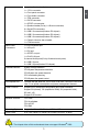
Table of Contents Chapter 1 Product Introduction Product Specifications...............................................................................2 Layout.......................................................................................................4 Back Panel Connectors.............................................................................5 Chapter 2 Hardware Install Install the CPU and CPU Cooler...............................................................
Configure . ........................................................................................66 About & Help.....................................................................................68 FOX LOGO..............................................................................................69 FOX DMI.................................................................................................70 Browser Configuration Utility .........................................................
Thank you for buying Foxconn A75A/A55A Series motherboard. Foxconn products are engineered to maximize computing power, providing only what you need for break-through performance. With advanced overclocking capability and a range of connectivity features for today multi-media computing requirements, A75A/A55A enables you to unleash more power from your computer.
1 1-1 Product Specifications CPU Support Husky Quad Core APU, Max processor power up to 100 W For the latest CPU information, please visit: http://www.foxconnsupport.com/cpusupportlist.
1 x TPM connector 1 x IR/CIR connector 1 x S/PDIF out connector 1 x Speaker header(Co-lay 1 x Buzzer conncetor) 6 x Serial ATA connectors 3 x USB 2.0 connectors(Hudson D2 chipset) 2 x USB 2.0 connectors(Hudson D3 chipset) 1 x USB 3.0 connectors(Hudson D3 chipset) 1 x Chassis intrusion alarm header 1 x COM connector 1 x PS/2 keyboard port 1 x VGA port 1 x DVI port 1 x S/PDIF our port 1 x RJ-45 LAN port 6-channel Audio ports(Co-lay 8-channel audio ports) 6 x USB 2.0 ports 2 x USB 3.
1 1-2 Layout 4 3 2 1 5 6 7 22 8 21 9 20 19 10 18 11 12 13 14 15 16 17 1. 4-pin ATX 12V Power Connector 14.24-pin ATX Power Connector 2. SYS_FAN Header 3. PCI Express Slots 15. IrDA/CIRConnector 16. TPM connector 17. Chassis Intrusion Alarm Header 18.COM1 Connector 19. DDR3 DIMM Slots 20. Chipset: Hudson D3(Co-lay Hudson D2) 21. CPU_FAN Headers 22. CPU Socket 4. PCI Slots 5. Front Audio Connector 6. CD_IN Connector 7. SPDIF-OUT Connector 8. Front USB 3.0 Connector 9. Front USB 2.
1-3 Back Panel Connectors 1 LAN Port 3 1 PS/2 Keyboard Port VGA Port Line Out 6 Line In Rear Speaker Subwoofer Side Speaker Microphone 2 4 USB Ports DVI-D Port 5 Optical SPDIF-Out Port 2 USB Ports 7 Audio Ports 1. PS/2 Keyboard Port Use the PS/2 port (purple) to connect a PS/2 keyboard. 2. USB Ports The USB port supports the USB 3.0 (blue) /2.0/1.1 specification. Use this port for USB devices such as an USB keyboard/mouse, USB printer, USB flash drive and etc.
1 7. Audio Ports For the definition of each audio port, please refer to the table below : Port 2-channel 4-channel 5.1-channel 7.
This chapter introduces the hardware installation process, including the installation of the CPU, memory, power supply, slots, pin headers and the mounting of jumpers. Caution should be exercised during the installation of these modules. Please refer to the motherboard layout prior to any installation and read the contents in this chapter carefully.
CA UT IO N 2-1 Install the CPU and CPU Cooler ! 2 ■ ■ ■ ■ ■ ■ Read the following guidelines before you begin to install the CPU : Make sure that the motherboard supports the CPU. Always turn off the computer and unplug the power cord from the power supply before installing the CPU to prevent hardware damage. Locate the Pin-1 of the CPU. The CPU cannot be inserted if oriented incorrectly. Apply an even and thin layer of thermal grease on the surface of the CPU.
3. When CPU is properly seated, push the CPU socket lever back to its locked position. 2 Install the CPU Cooler Follow the steps below to correctly install the CPU cooler. (The following procedures use Foxconn cooler as the example.) CA UT IO N ! 1. Apply and spread an even thermal grease on the surface of CPU. 2. Buckle the heatsink firmly at one 3. Buckle the heatsink at another side, and press the fasten lever down to tightly seat the cooler. 4.
CA UT IO N 2-2 Install the Memory ! 2 ■ ■ ■ Read the following guidelines before you begin to install the memory : Make sure that the motherboard supports the memory. It is recommended that memory of the same capacity, brand, speed, and chips be used. Always turn off the computer and unplug the power cord from the power outlet before installing the memory to prevent hardware damage. Memory modules have a foolproof design. A memory module can be installed in only one direction.
CA UT IO N Installing a Memory ! Before installing a memory module, make sure to turn off the computer and unplug the power cord from the power outlet to prevent damage to the memory module. Be sure to install DDR3 DIMMs on this motherboard. 96-Pin 144-Pin 2 Notch If you take a look at front side of memory module, it has asymmetric pin counts on both sides separated by a notch in the middle, so it can only fit in one direction.
CA UT IO N 2-3 Install an Expansion Card ! 2 ■ Make sure the motherboard supports the expansion card. Carefully read the manual ■ that came with your expansion card. Always turn off the computer and unplug the power cord from the power outlet before installing an expansion card to prevent hardware damage. PCI Express x1 PCI Express x16 PCI Follow the steps below to correctly install your expansion card in the expansion slot. 1. Locate an expansion slot that supports your card.
2-4 Install other Internal Connectors Power Connectors This motherboard uses an ATX power supply. In order not to damage any device, make sure all the devices have been installed properly before applying the power supply. 2 24-pin ATX power connector : PWR1 PWR1 is the ATX power supply connector. Make sure that the power supply cable and pins are properly aligned with the connector on the motherboard. Firmly plug the power supply cable into the connector and make sure it is secure.
2 Connect a 4-pin power plug Fan Connectors : SYS_FAN, CPU_FAN 1 CPU_FAN 2 There are three main fan headers on this motherboard. The fan speed can be controlled and monitored in “PC Health Status” section of the BIOS Setup. These fans can be automatically turned off after the system enters S3, S4 and S5 sleeping states. 1 GND POWER SENSE CONTROL CPU_FAN/SYS_FAN Speaker Connector : SPEAKER The speaker connector is used to connect speaker of the chassis.
S/PDIF Connector : SPDIF_OUT The connector is used for S/PDIF output. 1 2 +5V EMPTY SPDIF_OUT GND 3 4 SPDIF_OUT 2 Front Panel Connector : FP1 This motherboard includes one connector for connecting the front panel switch and LED Indicators. HDD-LED Hard Disk LED Connector (HDD-LED) Connect to the chassis front panel IDE indicator LED. It indicates the active status of the hard disks. This 2-pin connector is directional with +/- sign.
Audio Connector : F_AUDIO 2 The audio connector supports HD Audio standard. It provides the Front Audio output choice. PORT1_L PORT1_R PORT2_R SENSE_SEND PORT2_L 1 2 9 10 AUD_GND PRESENCE_J SENSE1_RETURN EMPTY SENSE2_RETURN F_AUDIO Audio Connector : CD_IN CD_IN is a Sony standard audio connector, it can be connected to a CD/DVD-ROM drive through a CD/DVD audio cable.
NC USB2.0 D+ USB2.0 D+ USB2.0 DGND USB2.0 DGND USB3.0 SS TX+ USB3.0 SS TX+ USB3.0 SS TX- USB3.0 SS TX- GND USB3.0 SS RX+ USB3.0 SS RX+ USB3.0 SS RX- USB3.0 SS RX+ VCC EMPTY VCC USB3.0 USB Connectors : F_USB In addition to the six USB ports on the rear panel, this product also provides two 10-pin USB headers on its motherboard.
2-5 Jumpers 2 For some features needed, users can change the jumper settings on this motherboard to modify them. This section explains how to use the various functions of this motherboard by changing the jumper settings. Users should read the following content carefully prior to modifying any jumper setting. Description of Jumpers 1. For any jumper on this motherboard, pin 1 can be identified by the bold silkscreen next to it. However, in this manual, pin 1 is simply labeled as “1”. 2.
This chapter tells how to change system settings through the BIOS Setup menus. Detailed descriptions of the BIOS parameters are also provided. You have to run the Setup Program when the following cases occur: 1. An error message appears on the screen during the system Power On Self Test (POST) process. 2. You want to change the default CMOS settings.
Enter BIOS Setup CA UT IO N The BIOS is the communication bridge between hardware and software, correctly setting up the BIOS parameters is critical to maintain optimal system performance. Power on the computer, when the message "Press to enter Setup, to boot menu" appears at the bottom of the screen, you can press key to enter SETUP.
21 3 ► Access Level It displays your current access level. If you enter system with a user password, it will dispaly “User”. If no password is set or you enter system with administrator password, this item will dispaly “Administrator”. ► Model Name This item shows the model name of this product. ► BIOS Version It displays the current BIOS version. User can check this information and discuss with the field service people if a BIOS upgrade is needed.
Fox Control Center Aptio Setup Utility - Copyright (C) 2011 American Megatrends, Inc. Main Advanced Chipset Boot Power Health Security Save & Exit F-Center Fox Control Center Super BIOS Protection Settings 3 Super BIOS Protect [Disable] Auto Detect PCI Clock [Disabled] ▶ Smart BIOS ▶ Fox Intelligent Stepping ▶ Voltage Options ▶ CPU Configuration → ←: Select Screen ↑ ↓: Select Item Enter: Select +/-: Change Opt.
Smart BIOS Aptio Setup Utility - Copyright (C) 2011 American Megatrends, Inc. F-Center Smart BIOS Smart Power LED [Disable] Smart Boot Menu [Enable] Smart Power LED Settings Version 2.11.1210. Copyright (C) 2011 American Megatrends, Inc. ► Smart Power LED Smart Power LED is a feature built on your motherboard to indicate different states during Power On Self Test (POST).
Fox Intelligent Stepping Aptio Setup Utility - Copyright (C) 2011 American Megatrends, Inc. F-Center 3 Fox Intelligent Stepping Spread Spectrum [Enable] Spread Spectrum Settings → ←: Select Screen ↑ ↓: Select Item Enter: Select +/-: Change Opt. F1: General Help F2: Previous Values F3: Optimized Defaults F4: Save & Reset ESC: Exit Version 2.11.1210. Copyright (C) 2011 American Megatrends, Inc.
CPU Voltage Options Aptio Setup Utility - Copyright (C) 2011 American Megatrends, Inc. F-Center Voltage Options Memory Voltage Control [Disabled] Memory Voltage Control Settings Version 2.11.1210. Copyright (C) 2011 American Megatrends, Inc. ► Memory Voltage This item is used to change the memeory voltage in a step of 100mV. The voltage can be incremented from +100mV to +400mV. 25 3 → ←: Select Screen ↑ ↓: Select Item Enter: Select +/-: Change Opt.
CPU Configuration Aptio Setup Utility - Copyright (C) 2011 American Megatrends, Inc.
Advanced BIOS Configuration Aptio Setup Utility - Copyright (C) 2011 American Megatrends, Inc. Main F-Center Chipset Boot Power Health Security Save & Exit Advanced Advanced BIOS Configuration Trusted Computing(TPM) Settings ▶ ▶ ▶ ▶ ▶ Trusted Computing North Bridge Onboard Device Configuration SATA Configuration Super IO Configuration Version 2.11.1210. Copyright (C) 2011 American Megatrends, Inc.
Trusted Computing Aptio Setup Utility - Copyright (C) 2011 American Megatrends, Inc. Advanced TPM Configuration TPM SUPPORT [Disabled] Current TPM Status Information NO TPM Hardware Enables or Disables TPM support. O.S. will not show TPM. Reset of platform is required. 3 → ←: Select Screen ↑ ↓: Select Item Enter: Select +/-: Change Opt. F1: General Help F2: Previous Values F3: Optimized Defaults F4: Save & Reset ESC: Exit Version 2.11.1210.
North Bridge Aptio Setup Utility - Copyright (C) 2011 American Megatrends, Inc. Advanced Integrated Graphics Memory Config → ←: Select Screen ↑ ↓: Select Item Enter: Select +/-: Change Opt. F1: General Help F2: Previous Values F3: Optimized Defaults F4: Save & Reset ESC: Exit Version 2.02.1205. Copyright (C) 2011 American Megatrends, Inc. ► Total Memory This item displays the current using memory information. ► Memory Slot 1/2/3/4 These items display the memory size installed on each slot.
Onboard Device Configuration Aptio Setup Utility - Copyright (C) 2011 American Megatrends, Inc. Advanced Onboard LAN Controller Onboard Device Configuration 3 Onboard LAN Controller [Enabled] Onboard LAN PXE OpROM [Disabled] Legacy USB Support [Enabled] Onboard USB Controller [Enabled] USB3.
SATA Configuration Aptio Setup Utility - Copyright (C) 2011 American Megatrends, Inc. Advanced SATA Configuration Onboard SATA Controller Onboard SATA Controller [Enabled] Onboard SATA Mode [Native IDE] ▶ ▶ ▶ ▶ ▶ SATA SATA SATA SATA SATA Port1: Port2: Port3: Port4: Port5: Not Not Not Not Not Present Present Present Present Present Version 2.02.1205. Copyright (C) 2011 American Megatrends, Inc.
Super IO Configuration Aptio Setup Utility - Copyright (C) 2011 American Megatrends, Inc. Advanced Set Parameters of CIR Controller(CIR) Super IO Configuration IT8728 3 Super IO Chip ▶ Serial Port 0 Configuration ▶ CIR Contrller Configuration → ←: Select Screen ↑ ↓: Select Item Enter: Select +/-: Change Opt. F1: General Help F2: Previous Values F3: Optimized Defaults F4: Save & Reset ESC: Exit Version 2.11.1210. Copyright (C) 2011 American Megatrends, Inc.
► Change Settings This item is used to select an optimal settings for the serial port. CIR Controller Configuration Aptio Setup Utility - Copyright (C) 2011 American Megatrends, Inc. Advanced Enable or Disable CIR Controller CIR Controller Configuration CIR Controller [Enabled] Device Settings IO=3E0h; IRQ=10; 3 Change settings → ←: Select Screen ↑ ↓: Select Item Enter: Select +/-: Change Opt.
Boot Configuration Aptio Setup Utility - Copyright (C) 2011 American Megatrends, Inc. Main Advanced Chipset Boot Power Health Security Save & Exit Boot Boot Configuration Bootup Numlock State Quiet Boot [On] Select the keyboard NumLock state [Enabled] 3 Boot Option Priorities → ←: Select Screen ↑ ↓: Select Item Enter: Select +/-: Change Opt. F1: General Help F2: Previous Values F3: Optimized Defaults F4: Save & Exit ESC: Exit Version 2.11.1210.
Power Management Setup Aptio Setup Utility - Copyright (C) 2011 American Megatrends, Inc.
Health 3 Aptio Setup Utility - Copyright (C) 2011 American Megatrends, Inc. Main Advanced Chipset Boot Power Health Security Exit Health [Disabled] Case Open Warning CPU Temperature : +54 C System Temperature : +37 C CPU Fan 1 Speed : 2738 RPM CPU Fan 2 Speed System Fan Speed : N/A CPU Vcore : +1.392 V +3.3 V : +3.371 V +12V SYS : +11.682 V +5V SYS : +5.225 V VDDR : +1.536 V VBAT : +3.
Security Aptio Setup Utility - Copyright (C) 2011 American Megatrends, Inc. Main Advanced Chipset Boot Power Health Security Exit Security Security Configuration Password Description If ONLY the Administrator’s password is set, then this only limits access to Setup and is only asked for when entering Setup. If ONLY the User’s password is set, then this is a power on password and must be entered to boot or enter Setup.
Exit Aptio Setup Utility - Copyright (C) 2011 American Megatrends, Inc. Main Advanced Chipset Boot Power Health Security Save Save & Exit Reset system setup after saving Save & Exit the changes. Save Changes and Reset Discard Changes and Reset Restore Defaults Boot Override 3 → ←: Select Screen ↑ ↓: Select Item Enter: Select +/-: Change Opt.
► Boot Override BIOS auto detect the presence of connected devices, select the device you want to boot from and press , then the system will directly boot from the selected devices. 39 3 ► Restore Defaults Optimal defaults are the best settings of this motherboard. Always load the Optimal defaults after updating the BIOS or after clearing the CMOS values. Select this option and press Enter, it will pop out a dialogue box to let you load the defaults.
The utility CD that came with the motherboard contains useful software and several utility drivers that enhance the motherboard features. This chapter includes the following information: ■ Utility CD content ■ Install driver and utility ■ FOX ONE ■ FOX LiveUpdate ■ FOX LOGO ■ FOX DMI ■ Browser Configuration Utility Note : Because each module is independent, so the section number will be reorganized and unique to each module, please understand.
Utility CD content This motherboard comes with one DVD, after installing the Oprating System, you can simply put it into your DVD-ROM drive, and the main menu will be displayed on your PC screen to guide you how to install. 1. Install Driver Use these options to install all the drivers for your system. You should install the drivers in order, and you need to restart your computer after all the drivers have been installed. 4 A. AMD Chipset Driver B. Realtek HDA Audio Driver C. Realtek 811X LAN Driver D.
Install driver and utility 1. Install Driver Use these options to install all the drivers for your system. You must click "AMD Chipset Driver" to install it first. After that, you can click ”One Click Setup” and then choose the items you want to install, or you can click on each individual driver to install it manually.
2. Install Utility Use these options to install additional software programs. 4 3. Utility Help Click this button to view the utility(FOX ONE, FOX LiveUpdate, FOX LOGO, FOX DMI) help manual.
FOX ONE FOX ONE is a powerful utility for easily modifying system settings. It also allows users to monitor various temperature values, voltage values, frequencies and fan speeds at any time. CA UT IO N With FOX ONE, you can : ■ Modify system performance settings, such as the CPU and memory bus speeds, CPU voltages, fan speeds, and other system performance options. ■ Monitor hardware temperatures, voltages, frequencies and fan speeds.
1. Main Page Show CPU Information Toolbar Alert Lamp Switch Button Skin Button Minimum Configuration Homepage Monitor Frequency/Voltage/Fan speed/Temperature value Toolbar Use the toolbar to navigate to other pages. Alert Lamp When the system is in healthy state, the color of alert lamp is green. When the system is in abnormal state, the alert lamp color is red. Switch Button Click this button, it will simplify the whole FOX ONE control panel to a smaller information bar (i.e.
Skin Button There are more choices of FOX ONE screen panels. Click this button, you can select your favorite skin (FOX ONE Panel). 4 Click the new skin picture to select the new skin Apply the changes Cancel the changes Exit Click this button to exit the program. Minimum Click this button to drop the FOX ONE to Windows system tray located at the lower right corner of your screen. Homepage Click this button to visit Foxconn motherboard website : http://www.foxconnchannel.
Configuration This menu allows you to configure : 1). Monitor interval (ms) : This is to define the interval of different messages of system settings which are to be displayed on Simple Mode screen. Minimum value is 1 second. 4 2). Simple Mode : To select which message of system settings are to be displayed in the Simple Mode. Messages such as CPU frequency, voltage...etc., they can be displayed one by one in Simple Mode. 3). F.I.S.
4 Step 1 : Click Calibration icon, a message pops out to ask for continue. Select Yes. Step 2 : After data is collected, it will ask you to restart your computer now. Later on, when the FOX ONE program is activated, and F.I.S. feature (in CPU Page) is also enabled, FOX ONE will automatically adjust your CPU clock according to your system loadings. (Loadings are like Power Gaming, Data Mining...etc.
2. CPU Page - CPU Control This page lets you select (or overclock) CPU clock to meet the current performance level of the system. The fastest and suitable CPU clock running for current system can be calculated by FOX ONE automatically or manually input by yourselves. Go to CPU page Adjust by manual Press Auto button to let FOX ONE check the highest CPU clock you can use.
You can see the system is 4 raising CPU clock until the system hangs. Push RESET button on the front panel of your system to restart the computer. Run FOX ONE program again, it will inform you the previous test found that 255MHz is the recommended CPU clock for your system. Click Yes to apply it to your system. Now, your system is running at a CPU clock of 215MHz.
FOX Intelligent Stepping (F.I.S., Optional) Select FOX Intelligent Stepping will allow your system to automatically adjust your CPU clock rate based on different system loadings. For example, if you select Power Gaming, CPU clock will be driven to run at its maximum speed. While in Energy Saving, CPU will lower down its speed to a minimum.
4. Limit Setting 4.1 Limit Setting - CPU Temperature This page lets you to set CPU high limit temperature and enable the alert function. Go to Limit Setting page Show current CPU temperature value 4 Enable alert function when the CPU temperature is higher than high limit value Show current high limit value of the CPU temperature Set high limit by dragging the lever 4.2 Limit Setting - System Temperature This page lets you to set system high limit temperature and enable the alert function.
4.3 Limit Setting - CPU Fan This page lets you to set CPU fan low limit rpm and enable the alert function. Show current CPU fan rpm value Enable alert function when the CPU fan runs slower than the low limit rpm value Set low limit rpm by dragging the lever 4.4 Limit Setting - System Fan This page lets you to set system fan low limit rpm and enable the alert function.
4.5 Limit Setting - NB Fan This page lets you to set NB fan low limit rpm and enable the alert function. Show current NB fan rpm value Enable alert function when the NB fan runs slower than low limit rpm value 4 Show current low limit rpm value of NB fan Set low limit rpm by dragging the lever 5. Voltage Page - Voltage Control (Optional) This page lets you set CPU voltage, memory voltage and North Bridge voltage manually. CPU voltage can be stepped up/down by a unit of 12.5mV, while memory is 0.
6. Fan Page - Fan Control This page lets you enable Smart Fan function or set the fan speed by manual. When Smart Fan is selected, you must use a 4-pin CPU cooler in your system.
FOX LiveUpdate FOX LiveUpdate is a useful utility to backup and update your system BIOS, drivers and utilities by local or online. Supporting Operating Systems : ■ Windows 2000 ■ Windows XP (32-bit and 64-bit) ■ Windows 2003 (32-bit and 64-bit) ■ Windows Vista (32-bit and 64-bit) Windows 7 (32-bit and 64-bit) 4 ■ Using FOX LiveUpdate : 1. Local Update 1-1 Local Update - BIOS Information This page lets you know your system BIOS information.
1-2 Local Update - Backup This page can backup your system BIOS. You can click “Backup”, and key in a file name, then click “Save” to finish the backup operation. The extension of this backup file is ".BIN" for Award BIOS and ".ROM" for AMI BIOS. Default directory is "C:\Desktop\My Documents" in Windows XP and "Documents" in Vista.
2. Online Update 2-1 Online Update - Update BIOS This page lets you update your system BIOS from Internet. Click “start”, it will search the new BIOS from Internet. Then follow the wizard to finish the update operation. Click here 4 Current information Search new BIOS from Internet Select BIOS to update Browse detailed information Update BIOS Close the window 2-2 Online Update - Update Driver This page lets you update your system drivers from Internet.
Select the driver to update Browse detailed information Install the selected driver Close the window 4 2-3 Online Update - Update Utility This page lets you update utilities from Internet. Click “start”, it will search the new utilities from Internet. Then follow the wizard to finish the update operation.
2-4 Online Update - Update All This page lets you update your system drivers from Internet. Click “start”, it will search all new BIOS/drivers/utilities from Internet. Then follow the wizard to finish the update operation.
3. Configure 3-1 Configure - option This page lets you set auto search options. After you enable the auto search function, FOX LiveUpdate will start its searching from Internet and if any qualified item found, it will pop out a message on the task bar to inform you to do the next step. Click here Set auto search options Select search which kind of versions Apply the changes Reset to default value Double click on the icon as show below, you can see the detailed information.
When you enable "Auto Search FOX LiveUpdate", if your FOX LiveUpdate version is older, it will auto search from internet and prompt you to install the new version. 4 Prompt you to install the new FOX LiveUpdate 3-2 Configure - System This page lets you set the location of download files and auto backup BIOS. determine if the FOX LiveUpdate can auto run when the system starts up.
3-3 Configure - Advance This page lets you select to flash BIOS / Boot Block and clear CMOS. If you choose Flash Boot Block, it means BIOS is not protective, and you must make sure the flash process is continuous and without any interruption. Click here Select which BIOS ROM to flash(Only available to motherboard with backup BIOS ROM ) Select to flash Boot Block CA UT IO N Apply the changes ! Reset to default value We recommend that you had better keep the default setting unchanged to avoid any damage.
FOX LOGO FOX LOGO is a simple and useful utility to backup, change and delete the boot time Logo. The boot Logo is the image that appears on screen during POST (Power-On Self-Test). 4 You can prepare a JPG image (1024x768) file, then use FOX LOGO to open it and change the boot time Logo. Boot time Logo will be displayed if you enable the BIOS "Quiet Boot" setting in "Advanced BIOS Features" menu.
FOX DMI FOX DMI is a full Desktop Management Interface viewer, and it provides three DMI data formats : Report, Data Fields and Memory Dump. With DMI information, system maker can easily analyze and troubleshoot your motherboard if there is any problem occurred.
Browser Configuration Utility Browser Configuration Utility is a browser search engine of Yahoo. We provide it to you for various choice. Supporting Operating Systems : ■ Windows XP (32-bit and 64-bit) ■ Windows Vista (32-bit and 64-bit) ■ Windows 7 (32-bit and 64-bit) 4 Using Browser Configuration Utility: 1. After installation, it will appear in the search menu of browser. You can use it directly. 2.
This chapter will cover two topics : ■ ■ Creating a Bootable Array - Installing a new Windows XP (or Vista,7) in a brand new RAID system. Creating a Non-Bootable Array - Existing Windows XP (or Vista,7) system with new RAID built as data storage.
Creating a Bootable Array - Installing a new Windows XP (or Vista,7) in a brand new RAID system. 5 1. Follow 5-1 to create a RAID driver diskette. 2. Follow 5-2 to set RAID enabled in BIOS. 3. Follow 5-3 to select a RAID array for use. 4. Follow 5-4 to Install a new Windows Operating System. What kinds of hardware and software you need here : 1. A floppy drive. 2. A DVD-ROM drive. 3. Several SATA hard disks. 4. A RAID driver diskette. 5. A motherboard driver CD.
RAID Configuration Introduction RAID (Redundant Array of Independent Disks) is a method for computer data storage schemes that divide and/or replicate data among multiple hard drives. RAID can be designed to provide increased data reliability (fault tolerance) or increased I/O (input/ output) performance, or both. The following RAID configurations are provided for users. There are three major key concepts in RAID: 1. Mirroring : The copying of data to more than one disk; 2.
RAID 0 (Striped) RAID 0 reads and writes sectors of data interleaved among multiple drives. If any disk member fails, it affects the entire array. The disk array data capacity is equal to the number of drive members times the capacity of the smallest member. RAID 0 does not support fault tolerance. 5 RAID 1 (Mirror) RAID 1 writes duplicate data onto a pair of drives and reads both sets of data in parallel.
Option ROM Utility The Option ROM Utility supports RAID 0, RAID 1, RAID5 and RAID10 functions. It allows you to get high performance with fault tolerance, big capacity, or data safety provided by different RAID functions. Here, we will use four SATA hard disks as an example to guide you through how to configure your RAID system. Assume four hard disks are connected to the motherboard : Lower SATA port of SATA1_SATA2 - HDS728090PLA380, 82.34GB Upper SATA port of SATA1_SATA2 - WDC WD1200JD-98HBB0, 120.
Two topics will be covered in the following sections : 1). Creating a Bootable Array - Installing a new Windows XP in a brand new RAID system. 2). Creating a Non-Bootable Array - Existing Windows XP system with new RAID built as data storage. CA UT IO N Install SATA Hard Disks before we continue : ■ Shut down your computer. ■ Install SATA hard disks into the drive bays, connect all power and SATA cables.
5-1 Create a RAID Driver Diskette If you want to install a brand new Windows XP on a RAID system, you need to create a RAID driver floppy diskette which will be used during Windows XP installation later. 1. Find a PC, put a diskette into its floppy drive A:, this diskette will be formatted later. Put the driver CD into DVD-ROM drive. 3. Click "GO" to start. 4. Select the desired destination FDD drive. It can be the default drive A: or any USB FDD. Click "OK" to continue. 5.
6. You can input a volume label for this diskette, click on "Start" to format. 5 7. Click on "OK" to go through this warning message. 8. Format finished. Click "OK" to continue copying of RAID driver into this diskette. 9. Check if the diskette contains the driver files.
5-2 RAID Enable in BIOS 1. Enter the BIOS setup by pressing key when boot up. 2. Select the “Integrated Peripherals” from the “Main menu”, then select the “IDE Configuration” menu and press to go to the configuration items. 3. Enable RAID function and individual SATA port for hard drive or DVD connection. 4. Press to save the setting then PC will reboot itself. 5-3 Select a RAID Array for Use Aptio Setup Utility - Copyright (C) 2011 American Megatrends, Inc.
Create RAID 0 (Striped) Here, we will show you how to create two RAID 0 Logical Drives (LD) by using two hard disks. 1. Select [2] from the main menu, " LD View Menu" appears. Option ROM Utility (c) 2008 Advanced Micro Devices, Inc. [ LD View Define LDMenu Menu] ] 5 < There is no any LD exist > [ Keys Available ] [↑] Up [↓] Down [PaUp/PaDn] Switch Page [Ctrl+C] Define LD [Enter] View LD [Ctrl+V] View Single Disk [ESC] Exit 2. Press [Crtl-C], the screen appears as below, select RAID 0. 3.
4. Another message prompts. Press [Ctrl-Y] to erase the RAID array. Option ROM Utility (c) 2008 Advanced Micro Devices, Inc.
6. Press [Ctrl-Y]. Input 80GB to select the first logical drive (LD1) and press [Enter]. Option ROM Utility (c) 2008 Advanced Micro Devices, Inc. [ Define LD Menu ] LD No LD Name RAID Mode RAID 0 1 Logical Drive LD 1 Stripe Block: 64 KB Gigabyte Boundary: OFF Drv RAID 0 Capacity(GB) 2 164.56 Fast Init: Cache Mode: ON WriteThru 5 [ Drives Assignment ] Channel :ID Drive Model Compatibilities Capacity(GB) Assignment 1 :Mas HDS728090PLA380 SATA 3G 82.
8. You can see in the previous example, about 40GB of Channel 1 and 2 hard disks were allocated. Select the remaining spaces from them for RAID 0 again. Option ROM Utility (c) 2008 Advanced Micro Devices, Inc.
10. Another message prompts. Press [Ctrl-Y] to erase the RAID array. Option ROM Utility (c) 2008 Advanced Micro Devices, Inc.
Create RAID 1 (Mirror) Here, we will show you how to create one Mirrored Logical Drives (LD) by using two hard disks. 1. Select [2] from the main menu, and " LD View Menu" appears. Then press [Crtl-C], the screen appears as below, select RAID 1. 2. Use [↓] key to select the hard disks, press [Space] key to change its assignment status to "Y". Press [Ctrl-Y] to save the setting. And a message prompts. You can select any of the two options. Here we select the latter option as an example.
4. The screen appears as below. Press any key to use the maximum capacity. Option ROM Utility (c) 2008 Advanced Micro Devices, Inc. [ Define LD Menu ] LD No LD Name RAID Mode LD 1 Stripe Block: NA Gigabyte Boundary: ON Logical Drive 1 Drv RAID 1 2 Fast Init: ON Cache Mode: WriteThru [ Drives Assignment ] Port :ID Drive Model Compatibilities Capacity(GB) Assignment 1 :Mas HDS728090PLA380 SATA 3G 82.34 N 2 :Mas WDC WD1200JD-98HBB0 SATA 1.5G 120.
Create RAID 10 (Striped Mirror) Here, we will show you how to create one Striped Mirror Logical Drives (LD) by using four hard disks. 1. Select [2] from the main menu, and " LD View Menu" appears. Then press [Crtl-C], the screen appears as below, select RAID 10. 2. Use [↓] key to select the hard disks, press [Space] key to change its assignment status to "Y". Press [Ctrl-Y] to save the setting. And a message prompts. You can select any of the two options. Here we select the latter option as an example.
4. The screen appears as below. Press any key to use the maximum capacity. Option ROM Utility (c) 2008 Advanced Micro Devices, Inc. [ Define LD Menu ] LD No LD Name RAID Mode LD 1 Stripe Block: NA Gigabyte Boundary: ON Logical Drive 1 Drv RAID 10 4 Fast Init: ON Cache Mode: WriteThru [ Drives Assignment ] Port :ID Drive Model Compatibilities Capacity(GB) Assignment 1 :Mas HDS728090PLA380 SATA 3G 82.34 N 2 :Mas WDC WD1200JD-98HBB0 SATA 1.5G 120.
Create JBOD Here, we will show you how to create a JBOD Logical Drives (LD) by using four hard disks. 1. Select [2] from the main menu, and " LD View Menu" appears. Then press [Crtl-C], the screen appears as below, select JBOD. Option ROM Utility (c) 2008 Advanced Micro Devices, Inc.
3. Another message prompts. Press [Ctrl-Y] to erase the RAID array. Option ROM Utility (c) 2008 Advanced Micro Devices, Inc. [ Define LD Menu ] LD No LD Name RAID Mode LD 1 Stripe Block: NA Gigabyte Boundary: ON Logical Drive 1 Drv JBOD 4 Fast Init: ON Cache Mode: WriteThru [ Drives Assignment ] Port :ID Drive Model Assignment Fast InitializationCompatibilities Option has beenCapacity(GB) selected 1 :Mas HDS728090PLA380 It will erase the MBRSATA data of3G the disks.
5-4 Install a New Windows XP Assume a Mirrored array (249.99GB) was created as introduced in section 5-3, after the system restarts : 1. Press to enter BIOS Setup during POST. 2. Insert the Windows installation CD into the optical drive. 3. Set the “1st Boot Device” to “CD/DVD-ROM”, save changes and exit BIOS. CMOS Setup Utility - Copyright (C) 1985-2006, American Megatrends, Inc.
5. After some files are copied to your system, the following picture appears, press to continue the specific driver installation. Windows Setup 5 Setup could not determine the type of one or more mass storage devices installed in your system, or you have chosen to manually specify an adapter.
7. There are two drivers, for your 32-bit XP system, press [Enter] to select the first driver - "AMD AHCI Compatible RAID Controller-x86 platform". Windows Setup You have chosen to configure a SCSI Adapter for use with Windows, using a device support disk provided by an adapter manufacturer. Select the SCSI Adapter you want from the following list, or press ESC to return to the previous screen.
9. Windows will display the partition of your system. As we are using a Mirrored RAID array as an example, its size 232.88GB is now displayed as 238410MB. You can press [C] to create partitions as many as you wish, assign them C:, D: or E: logical drive names. (Note : 238410MB/1024 = 232.82GB) Windows XP Professional Setup The following list shows the existing partitions and unpartitioned space on this computer. Use the UP ad DOWN ARROW keys to select an item in the list.
5-5 Setting Up a Non-Bootable RAID Array This section assumes the following setup : ■ Boot Disk with Windows XP installed : One hard disk HDS728090PLAT20 (80GB) is connected to the IDE channel, and set to Master. ■ A Mirrored RAID Array Disk : Two SATA hard disks are configured as a mirrored RAID1 array, they are : Hitachi HDT725025VLA3, (250.05GB) connected to SATA port2 of the motherboard. Seagate ST3320620AS, (320.07GB) connected to SATA port3. ■ A SATA DVD Drive : A DVD drive connected to SATA port1.
2. Select a RAID array for use (also can refer to section 5-3) After rebooting your computer, you will see the RAID software prompting you to press [Ctrl-F]. Press [Ctrl-F] to enter the Option ROM Utility and configure the mirrored RAID array as described in the 5-3 section. Finally, you can reach this step as depicted. Option ROM Utility (c) 2008 Advanced Micro Devices, Inc. [ LD View Define LDMenu Menu] ] LD No RAID Mode LD LD 1 1 RAID RAID 1 0 Drv Capacity(GB) 2 2 249.99 249.
5. After the AMD RAID driver is installed, it will ask you to click "Finish" to restart your computer. 5 6. When Windows starts, a message is prompting you to reboot again. Click "Yes" to restart your computer.
5 7. After PC starts, the RAID array is now ready to be initialized under Windows. Launch Computer Management by clicking Start -> (Settings ->) Control Panel then open the Administrative Tools folder and double click on Computer Management. Click Disk Management (under the Storage section). The Initialize and Convert Disk Wizard appears. Click "Next" to continue. The RAID array is named as Disk1 and its status is unknown and not initialized. 8. A "Select Disks to Initialize" window will appear.
11. The Computer Management window appears. The actual disks listed will depend on your system. In below figure, you can see there is a 232.82 GB unallocated partition. You must format the unallocated disk space before using it. Right click "Unallocated space", select "New Partition…" and follow the Wizard instructions. 5 12. When "New Partition Wizard" appears, click "Next" to continue. 13. When "Primary partition" screen appears, click "Next" to continue. 14.
5 17. The format of disk array (Disk1) is in processing. 18. Format completed, now you can start using your RAID array.