
User Manual
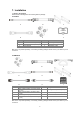
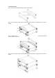
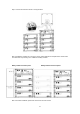
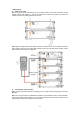
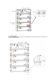

Table Of Contents

13
7.5 Wiring Steps
A. Battery power cable
Step 1: Connect the power cable starting from the first battery module in series with other battery modules
(Orange opposite, black negative). A ‘click’ sound indicates the connections are secured. The positive and
negative connection of the battery cable is shown in below.
Step 2: Measure voltage value: After all battery modules are connected in series, use a multimeter to measure
the DC voltage on DC terminal. The total voltage should be N *52±10V (N is the total number of battery module).
Please refer to the picture below for voltage test.
B. Communication cable connection:
Step 1: Take the main positive cable (two orange plugs), the main negative line (two black plugs) to connect the
BMS BOX.
Step 2: Then connect the 485 on the BMS BOX to the RS485-1 of the first battery module, connect the RS485-1
of the previous battery module to RS485-2 of the next battery module, leave the last module’ s RS485-2 vacant.
Wiring shall be connected in the sequence as shown in below.