
User Manual
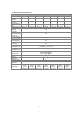
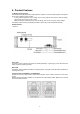
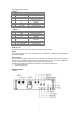
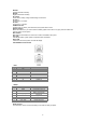
Table Of Contents

8
BAT IN +
Positive electrode of battery.
BAT IN -
Negative electrode of battery.
DC switch
Power switch, battery charge and discharge circuit switch.
DC OUT +
Connect bat + of inverter.
DC OUT -
Connect bat - of inverter.
POWER switches
System power on switch, press this switch, the system starts to work.
B-Start switches
Black start switches, if you want to start the battery system when there is no grid, press this switch first
and then power on the system.
DIP switches
BMS relies on DIP switches to confirm the number of HV2600 in the system.
SOC LED
LED display battery system power and specific alarm information.
Alarm LED
If there is a fault in the system, the LED will display.
CAN & RS485 communication
- CAN
Pin
Function Definitions
Function Declaration
1
NC
2
GND
Power/signal ground
3
B1
RS485-B
4
CANL
CANL
5
CANH
CANH
6
NC
7
NC
8
A1
RS485-A
- RS485
Pin
Function Definitions
Function Declaration
1
GND
Power/signal ground
2
GND
Power/signal ground
3
P+
Signal P+
4
VCC_485_2
Wake up the power
supply+5v
5
N-
Signal N-
6
B2
RS485-B
7
A2
RS485-A
8
VCC_485
power supply+5v
Earth Terminal
This terminal is used to connect the battery to the earth for safety purposes.