User Manual HV 2600 In order to prevent improper operation before use, please carefully read this manual.
Table of Contents 1. Introduction ....................................................................................................................... 1 2. Symbols ............................................................................................................................ 1 3. Safety ................................................................................................................................ 2 3.1 Handling ...............................................................
1. Introduction The document describes the installation, commissioning, maintenance and troubleshooting of the following high voltage battery listed below. HV2600 Note: HV2600 = 2.6kWh High Voltage The battery chemistry of these products is Lithium Iron Phosphate. This manual is designed for qualified personnel only. The tasks described in this document should be performed by authorized and qualified technicians only. After Installation the Installer must explain the user manual to the end user. 2.
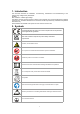
Caution, risk of electric shock, energy storage timed discharge. 3. Safety Any work on the Batteries should be handled by authorized technicians and hence it is understood that the technicians should familiarize themselves with the contents of this manual before any maintenance or installation is carried out on the system. 3.1 Handling Do not expose battery to open flame. Do not place the product under direct sunlight. Do not place the product near flammable materials.
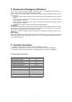
4. Response to Emergency Situations The batteries comprise of multiple batteries connected in series. It is designed to prevent hazards or failures. However, Fox cannot guarantee their absolute safety. Under exposure to the internal materials of the battery the following recommendations should be carried out by the user. · If there has been inhalation, please leave the contaminated area immediately and seek medical attention.
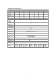
5.2 BMS Specifications Specifications for BMS BOX Model NO. Operating voltage range(V) Max. charge/discharge current (A) Total voltage measurement accuracy Total voltage measurement channel Current measurement range Insulation measurement accuracy Communication interfaces Available SOC range Charge/Discharge efficiency (%) Operating temperature (°C) Storage temperature (°C) Humidity Weight (kg) Dimensions (L*W*H) (mm) BMS-BOX 60-500VDC 50A/50A ±1.
5.3 Battery System Specifications Specifications for Battery System System model HS5.2 HS7.8 The number of 2*HV2600 3*HV2600 batteries Normal 102.4 153.6 voltage(V) Normal capacity 50 50 (Ah) Voltage range(V) 80-116.8 120-175.2 Recommended charging current(A) Max.
6. Product Features 6.1 Battery System Features The batteries have been fitted with multiple protection systems to ensure the safe operation of the system.
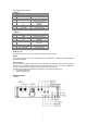
Pin configuration is as follows: - RS485-1 Pin Function Definitions 1 GND 2 GND 3 B2 4 A2 5 VCC_485_2 6 7 8 P+ NVCC_485 - RS485-2 Pin Function Definitions 1 GND 2 GND 3 B2 4 A2 5 VCC_485_2 6 7 8 P+ NVCC_485_NEXT Function Declaration Power/signal ground Power/signal ground RS485-B RS485-A Wake up the power supply+5v Signal P+ Signal Npower supply+5v Function Declaration Power/signal ground Power/signal ground RS485-B RS485-A Wake up the power supply+5v Signal P+ Signal Npower supply+5v Earth Termin
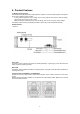
BAT IN + Positive electrode of battery. BAT IN Negative electrode of battery. DC switch Power switch, battery charge and discharge circuit switch. DC OUT + Connect bat + of inverter. DC OUT Connect bat - of inverter. POWER switches System power on switch, press this switch, the system starts to work. B-Start switches Black start switches, if you want to start the battery system when there is no grid, press this switch first and then power on the system.
7. Installation 7.1 Items in the package Please check if following items are including with the package: For HV2600 A B C Quick Installation Guide D Number A B C E Items Communication cable (0.21m) Battery power cable (0.19m) Fixing bracket F Number D E F Items Grounding cable (0.19m) Mounting screw pack Installation guide Note: item C is provide separately, not including in battery package. Please contact your dealer if you do not have it.
7.2 Clearance Make sure to leave a space of at least 300 mm. A clearance of at least 300 mm must be Ieft around the battery pack for proper cooling. Note: Make sure that the battery pack is always exposed to the ambient air. The battery pack is cooled by natural convection. If the battery pack is entirely or partially covered or shielded, it may cause the battery pack to stop operating. 7.3 Tools The following tools will be required to install the BMS BOX and the battery.
7.4 Installation Steps Step 1: Place the front bracket and back bracket as shown below. Step 2: Insert the battery module into the bracket from front horizontally, and tighten the four screws on the side. Step 3: Locate the brackets for the second battery on top of the first pair of the bracket and fasten the connecting button on the side. Step 4: Insert the battery module into the bracket from front horizontally, and tighten the four screws on the side.
Step 5: Connect the inverter as shown in the figure below. Note: If the Battery modules are more than 4 pieces, please separate into multiple stacks. Please make sure each stack only including max. 1 BMS and 4 battery modules. Battery modules less than 4 pieces: Battery modules more than 4 pieces: Note: For another installation, please refer to the All-In-One user manual.
7.5 Wiring Steps A. Battery power cable Step 1: Connect the power cable starting from the first battery module in series with other battery modules (Orange opposite, black negative). A ‘click’ sound indicates the connections are secured. The positive and negative connection of the battery cable is shown in below. Step 2: Measure voltage value: After all battery modules are connected in series, use a multimeter to measure the DC voltage on DC terminal.
C. Grounding cable: Connect the grounding cable to ensure that all batteries are grounded. Wiring shall be connected in the sequence as shown in below.
7.6 System Start up · · · 1. · · When the grid connected system is started, the inverter should be turned on first to avoid the current pulse of the inverter increasing to the battery pack. All installation and operation must comply with local electrical standards. Check all power cables and communication cables carefully. Turn on the POWER switch Before starting, please dial DIP to the correct position. DIP represents the number of HV2600 in the system.
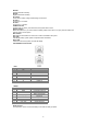
- SOC LED indication Status =100% >100%>soc>=75% 75%>soc>=50% 50%>soc>=25% 25%>soc>=0 Charge Discharge On On On On On On On On Flash On On On On On On On Off Off Flash On On On On On Off Off Off Off Flash On On On Off Off Off Off Off Off Off On Stand By Off - SOC LED fault message Fault Differential pressure fault Under voltage fault Over temperature fault Under temperature fault Discharge over current Charge over current Over voltage fault MCU fault AFE fau
9. Exclusion The warranty shall not cover the defects caused by normal wear and tear, inadequate maintenance, handling, storage faulty repair, modifications to the battery or pack by a third party other than Fox or Fox agent, failure to observe the product specification provided herein or improper use or installation, including but not limited to the following. · Damage during transport or storage. · Incorrect Installation of battery into pack or maintenance.
The copyright of this manual belongs to FOXESS CO., LTD. Any corporation or individual should not plagiarize, partially or fully copy (including software, etc.), and no reproduction or distribution of it in any form or by any means is permitted. All rights reserved. FOXESS CO., LTD. Add: No.939, Jinhai Third Road, New Airport Industry Area, Longwan District, Wenzhou, Zhejiang, China Tel: 0510- 68092998 WWW.FOX-ESS.COM V3.