
- Foundry Network Device Installation Guide


C
ABLES
B-6 © 2003 Foundry Networks, Inc. February 2003
Console Port Pin Assignments
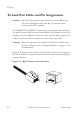
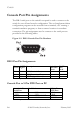
The DB-9 serial port on the switch’s rear panel is used to connect to the
switch for out-of-band console configuration. The on-board menu-driven
configuration program can be accessed from a terminal, a PC running a
terminal emulation program, or from a remote location via a modem
connection. The pin assignments used to connect to the serial port are
provided in the following tables.
Figure 2-2. DB-9 Console Port Pin Numbers
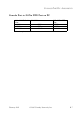
DB-9 Port Pin Assignments
Console Port to 9-Pin DTE Port on PC
EIA
Circuit
CCITT
Signal
Description Switch’s
DB9 DTE
Pin #
PC DB9
DTE
Pin #
BB 104 RxD (Received Data) 2 2
BA 103 TxD (Transmitted Data) 3 3
AB 102 SGND (Signal Ground) 5 5
No other pins are used.
Switch’s 9-Pin
Serial Port
Null Modem PC’s 9-Pin
DTE Port
2 RXD <---------RXD ------------ 3 TxD
3 TXD -----------TXD ----------> 2 RxD
5 SGND -----------SGND ---------- 5 SGND
No other pins are used.