Foundry EdgeIron 4802CF Installation Guide 2100 Gold Street P.O. Box 649100 San Jose, CA 95164-9100 Tel 408.586.1700 Fax 408.586.1900 www.foundrynetworks.
Copyright © 2003 Foundry Networks, Inc. All rights reserved. No part of this work may be reproduced in any form or by any means – graphic, electronic or mechanical, including photocopying, recording, taping or storage in an information retrieval system – without prior written permission of the copyright owner. The trademarks, logos and service marks ("Marks") displayed herein are the property of Foundry or other third parties.
COMPLIANCES FCC - Class A This equipment generates, uses, and can radiate radio frequency energy and, if not installed and used in accordance with the instruction manual, may cause interference to radio communications. It has been tested and found to comply with the limits for a Class A computing device pursuant to Subpart B of Part 15 of FCC Rules, which are designed to provide reasonable protection against such interference when operated in a commercial environment.
EDGEIRON 4802CF INSTALLATION GUIDE Immunity: • Product family standard according to EN 55024:1998 • Electrostatic Discharge according to EN 61000-4-2:1995 (Contact Discharge: ±4 kV, Air Discharge: ±8 kV) • Radio-frequency electromagnetic field according to EN 61000-4-3:1996 (80 - 1000 MHz with 1 kHz AM 80% Modulation: 3 V/m) • Electrical fast transient/burst according to EN 61000-4-4:1995 (AC/ DC power supply: ±1 kV, Data/Signal lines: ±0.
COMPLIANCES Taiwan BSMI Class A Australia AS/NZS 3548 (1995) - Class A ACN 066 352010 Contact Foundry Networks at: Foundry Networks, Inc. 2100 Gold Street P.O. Box 649100 San Jose, CA 95164-9100 February 2003 © 2003 Foundry Networks, Inc.
EDGEIRON 4802CF INSTALLATION GUIDE Safety Compliance Warning: Fiber Optic Port Safety CLASS I LASER DEVICE When using a fiber optic port, never look at the transmit laser while it is powered on. Also, never look directly at the fiber TX port and fiber cable ends when they are powered on. Avertissment: Ports pour fibres optiques - sécurité sur le plan optique Ne regardez jamais le laser tant qu’il est sous tension.
COMPLIANCES Wichtige Sicherheitshinweise (Germany) 1. Bitte lesen Sie diese Hinweise sorgfältig durch. 2. Heben Sie diese Anleitung für den späteren Gebrauch auf. 3. Vor jedem Reinigen ist das Gerät vom Stromnetz zu trennen. Verwenden Sie keine Flüssigoder Aerosolreiniger. Am besten eignet sich ein angefeuchtetes Tuch zur Reinigung. 4. Die Netzanschlu ßsteckdose soll nahe dem Gerät angebracht und leicht zugänglich sein. 5. Das Gerät ist vor Feuchtigkeit zu schützen. 6.
EDGEIRON 4802CF INSTALLATION GUIDE 8 © 2003 Foundry Networks, Inc.
CONTENTS 1 About This Guide . . . . . . . . . . . . . . . . . . . . . . . . . . . . .1-1 Audience . . . . . . . . . . . . . . . . . . . . . . . . . . . . . . . . . . . . . . . . . . . . . . . . . . Nomenclature . . . . . . . . . . . . . . . . . . . . . . . . . . . . . . . . . . . . . . . . . . . . . . How to Get Help . . . . . . . . . . . . . . . . . . . . . . . . . . . . . . . . . . . . . . . . . . . Foundry Networks Technical Support . . . . . . . . . . . . . . . . . . . . Web Access . . . . . . . . . .
CONTENTS 1000 Mbps Gigabit Ethernet Collision Domain . . . . . . . . . . . . . 100 Mbps Fast Ethernet Collision Domain . . . . . . . . . . . . . . . . Maximum Fast Ethernet Cable Distance . . . . . . . . . . . . . . . 10 Mbps Ethernet Collision Domain . . . . . . . . . . . . . . . . . . . . . Maximum Ethernet Cable Distance . . . . . . . . . . . . . . . . . . . Application Notes . . . . . . . . . . . . . . . . . . . . . . . . . . . . . . . . . . . . . . . . . . 4 Installing the Switch . . . . . . . . . .
CONTENTS Adjusting Existing Category 5 Cabling to Run 1000BASE-T . . . . . . . . . . . . . . . . . . . . . . . . . . . B-5 Console Port Pin Assignments . . . . . . . . . . . . . . . . . . . . . . . . . . . . . . . . B-6 DB-9 Port Pin Assignments . . . . . . . . . . . . . . . . . . . . . . . . . . . . . B-6 Console Port to 9-Pin DTE Port on PC . . . . . . . . . . . . . . . . . . . B-6 Console Port to 25-Pin DTE Port on PC . . . . . . . . . . . . . . . . . . B-7 C Specifications . . . . . . . . . . . . . .
CONTENTS 12 © 2003 Foundry Networks, Inc.
CHAPTER 1 ABOUT THIS GUIDE Audience This guide is for system administrators with a working knowledge of network management. You should be familiar with switching and networking concepts. Nomenclature This guide uses the following typographical conventions to show information: Italic highlights the title of another publication and occasionally emphasizes a word or phrase. code shows text that must be entered exactly as it appears in this guide.
EDGEIRON 4802CF INSTALLATION GUIDE Web Access Point your browser to the following URL: http://www.foundrynetworks.com. Navigate to Services/Technical Support. Click the Login button, then enter your user name and password to gain access to the Foundry support site. E-mail Access Technical requests can also be sent to the e-mail address: support@foundrynet.com Telephone Access ◆ 1.877.TURBOCALL (887.2622): United States ◆ 1.408.586.
CHAPTER 2 ABOUT THE EDGEIRON 4802CF Overview Foundry’s EdgeIron 4802CF is an intelligent Fast Ethernet switch with 48 10BASE-T/100BASE-TX ports and two 10/100/1000BASE-T combo ports that operate in combination with 2 Small Form Factor Pluggable (SFP) transceiver slots. This switch can easily tame your network with full support for Spanning Tree Protocol, Multicast Switching, Virtual LANs, and Layer 2/3/4 CoS services. Figure 2-1.
ABOUT THE EDGEIRON 4802CF Switch Architecture The EdgeIron 4802CF employs a wire-speed, non-blocking switching fabric. This permits simultaneous wire-speed transport of multiple packets at low latency on all ports. This switch also features full-duplex capability on all ports, which effectively doubles the bandwidth of each connection. Switching Method The switch uses store-and-forward switching to ensure maximum data integrity.
DESCRIPTION OF HARDWARE Description of Hardware 10BASE-T/100BASE-TX Ports These are dual-speed RJ-45 ports. Because all ports on this switch support automatic MDI/MDI-X operation, you can use straight-through cables for all network connections to PCs or servers, or to other switches or hubs. (See“100BASE-TX/10BASE-T Pin Assignments” on page B-3.
ABOUT THE EDGEIRON 4802CF Status LEDs The LEDs, which are located on the front panel for easy viewing, are shown below and described in the following table. Figure 2-2. Port and System LEDs Port Status LEDs LED Condition Status Fast Ethernet Ports (Ports 1~48) Link/Act.* On/Flashing Amber Port has established a valid 10 Mbps network connection. Flashing indicates activity. On/Flashing Green Port has established a valid 100 Mbps network connection. Flashing indicates activity.
DESCRIPTION OF HARDWARE Port Status LEDs LED FDX* (all ports) Condition Status On Green Port is operating in full-duplex mode. Off Port is operating in half-duplex mode. *Use the Mode Select button to select the LED display mode. System Status LEDs LED Power RPU Diag. February 2003 Condition Status On Green The unit’s internal power supply is operating normally. On Red The unit’s internal power supply has failed. Off The unit has no power connected.
ABOUT THE EDGEIRON 4802CF Optional Redundant Power Unit Foundry provides an optional Redundant Power Unit (RPU) that can supply power to the switch in the event of failure of the internal power supply. Power Supply Receptacles There are two power receptacles on the rear panel of the switch. The standard power receptacle is for the AC power cord. The receptacle labeled “RPU” is for the optional Redundant Power Unit (RPU). Figure 2-3. Power Supply Receptacles 2-6 © 2003 Foundry Networks, Inc.
FEATURES AND BENEFITS Features and Benefits Connectivity ◆ 48 dual-speed ports for easy Fast Ethernet integration and for protection of your investment in legacy LAN equipment ◆ Two 10/100/1000BASE-T auto-sensing Gigabit Ethernet switching ports that operate in combination with two Small Form Factor Pluggable (SFP) transceiver slots ◆ Auto-negotiation enables each RJ-45 port to automatically select the optimum communication mode (half or full duplex) if this feature is supported by the attached device
ABOUT THE EDGEIRON 4802CF ◆ Includes support for an optional Redundant Power Unit ◆ Desktop or rack-mountable Management 2-8 ◆ “At-a-glance” LEDs for easy troubleshooting ◆ Network management agent: • Supports Telnet, SNMP/RMON and Web-based interface • Supports out-of-band RS-232 console port (VT100) • Software upload via TFTP • Supports BOOTP and DHCP for IP address assignment • Spanning Tree Protocol • Support for up to 255 IEEE 802.1Q based tagged VLANs with GVRP • IEEE 802.
CHAPTER 3 NETWORK PLANNING Introduction to Switching A network switch allows simultaneous transmission of multiple packets via non-crossbar switching. This means that it can partition a network more efficiently than bridges or routers. The switch has, therefore, been recognized as one of the most important building blocks for today’s networking technology.
NETWORK PLANNING Application Examples The EdgeIron 4802CF is not only designed to segment your network, but also to provide a wide range of options in setting up network connections. Some typical applications are described below. Collapsed Backbone The EdgeIron 4802CF is an excellent choice for mixed Ethernet and Fast Ethernet installations where significant growth is expected in the near future.
APPLICATION EXAMPLES Central Wiring Closet With 50 parallel bridging ports (i.e., 50 distinct collision domains), the EdgeIron 4802CF can collapse a complex network down into a single efficient bridged node, increasing overall bandwidth and throughput. In the figure below, the 10BASE-T/100BASE-TX ports on the EdgeIron 4802CF are providing 100 Mbps connectivity for up to 48 segments. In addition, the switch is also connecting servers at 200 Mbps. Figure 3-2.
NETWORK PLANNING Remote Connections with Fiber Cable Fiber optic technology allows for longer cabling than any other media type. A 1000BASE-LX SFP transceiver link can connect to a site up to 5 km away. This allows the EdgeIron 4802CF to serve as a collapsed backbone, providing direct connectivity for a widespread LAN. A Gigabit SFP transceiver can also be used for a high-speed connection between floors in the same building, or to connect to other buildings in a campus setting.
APPLICATION EXAMPLES Making VLAN Connections VLANs can be based on port groups, or each data frame can be explicitly tagged to identify the VLAN group it belongs to. When using port-based VLANs, ports can either be assigned to one specific group or to all groups. Port-based VLANs are suitable for small networks. A single switch can be easily configured to support several VLAN groups for various organizational entities (such as Finance and Marketing).
NETWORK PLANNING Connectivity Rules When adding hubs (repeaters) to your network, please follow the standard connectivity rules for Ethernet, Fast Ethernet, and Gigabit Ethernet. However, note that because switches break up the path for connected devices into separate collision domains, you should not include the switch or connected cabling in your calculations for cascade length involving other devices.
CONNECTIVITY RULES 100 Mbps Fast Ethernet Collision Domain Maximum Fast Ethernet Cable Distance Type Cable Type Max. Cable Length 100BASE-TX Category 5 100-ohm UTP or STP 100 m (328 ft.) 100BASE-FX 50/125 or 62.5/125 micron core Multimode multimode fiber (MMF) 2 km (1.24 miles) 10 Mbps Ethernet Collision Domain Maximum Ethernet Cable Distance Cable Type Maximum Length Twisted Pair, Categories 3, 4, 5 100 m (328 ft) February 2003 © 2003 Foundry Networks, Inc.
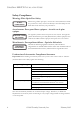
NETWORK PLANNING Application Notes 1. Full-duplex operation only applies to point-to-point access (such as when a switch is attached to a workstation, server or another switch). When the switch is connected to a hub, both devices must operate in half-duplex mode. 2. Avoid using flow control on a port connected to a hub unless it is actually required to solve a problem. Otherwise back pressure jamming signals may degrade overall performance for the segment attached to the hub. 3.
CHAPTER 4 INSTALLING THE SWITCH Selecting a Site EdgeIron 4802CF units can be mounted in a standard 19-inch equipment rack or on a flat surface. Be sure to follow the guidelines below when choosing a location. ◆ The site should: • be at the center of all the devices you want to link and near a power outlet.
INSTALLING THE SWITCH Equipment Checklist After unpacking the EdgeIron 4802CF, check the contents to be sure you have received all the components. Then, before beginning the installation, be sure you have all other necessary installation equipment.
MOUNTING Mounting An EdgeIron 4802CF unit can be mounted in a standard 19-inch equipment rack or on a desktop or shelf. Mounting instructions for each type of site follow. Rack Mounting Before rack mounting the switch, pay particular attention to the following factors: ◆ Temperature: Since the temperature within a rack assembly may be higher than the ambient room temperature, check that the rack-environment temperature is within the specified operating temperature range. (See page C-2.
INSTALLING THE SWITCH To rack-mount devices: 1. Attach the brackets to the device using the screws provided in the Bracket Mounting Kit. Figure 4-1. Attaching the Brackets 2. Mount the device in the rack, using four rack-mounting screws (not provided). Figure 4-2. Installing the Switch in a Rack 4-4 © 2003 Foundry Networks, Inc.
MOUNTING 3. If installing a single switch only, turn to “Connecting to a Power Source” at the end of this chapter. 4. If installing multiple switches, mount them in the rack, one below the other, in any order. 5. If also installing RPUs, mount them in the rack below the other devices. Desktop or Shelf Mounting 1. Attach the four adhesive feet to the bottom of the first switch. Figure 4-3. Attaching the Adhesive Feet 2.
INSTALLING THE SWITCH Connecting to a Power Source To connect a device to a power source: 1. Insert the power cable plug directly into the receptacle located at the back of the device. Figure 4-4. Power Receptacle 2. Plug the other end of the cable into a grounded, 3-pin socket. Note: For International use, you may need to change the AC line cord. You must use a line cord set that has been approved for the receptacle type in your country. 3.
CHAPTER 5 MAKING NETWORK CONNECTIONS Connecting Network Devices The EdgeIron 4802CF is designed to interconnect multiple segments (or collision domains). It may be connected to network cards in PCs and servers, or to hubs, switches or routers. Note: Before connecting cables, you may want to first configure the Spanning Tree Protocol to avoid network loops. Refer to the User Guide for more information.
MAKING NETWORK CONNECTIONS Note: If auto-negotiation is disabled for an RJ-45 port, the auto-MDI/ MDI-X pin signal configuration is also disabled. See Appendix B for further information on cabling. Caution: Do not plug a phone jack connector into an RJ-45 port. This will damage the switch. Use only twisted-pair cables with RJ-45 connectors that conform to FCC standards. Connecting to PCs, Servers, Hubs and Switches 1. Attach one end of a twisted-pair cable segment to the device’s RJ-45 connector.
TWISTED-PAIR DEVICES Notes: 1. When connected to a shared collision domain (such as a hub with multiple workstations), switch ports must be set to half-duplex mode. 2. Avoid using flow control on a port connected to a hub unless it is actually required to solve a problem. Otherwise back pressure jamming signals may degrade overall performance for the segment attached to the hub. 3.
MAKING NETWORK CONNECTIONS Figure 5-2. Wiring Closet Connections Equipment Rack (side view) Switch Punch-Down Block Patch Panel Wall 5-4 © 2003 Foundry Networks, Inc.
APPENDIX A TROUBLESHOOTING Diagnosing Switch Indicators Troubleshooting Chart Symptom Action Power LED is Off • Internal power supply is disconnected. • Check connections between the switch, the power cord, and the wall outlet. • Contact Technical Support. Power LED is Red • Internal power supply has failed. Contact your local dealer for assistance. Link LED is Off • Verify that the switch and attached device is powered on.
TROUBLESHOOTING check for loose power connections, power losses or surges at the power outlet, and verify that the fans on the unit are unobstructed and running prior to shutdown. If you still cannot isolate the problem, then the internal power supply may be defective. In this case, contact Technical Support for assistance. Installation Verify that all system components have been properly installed.
APPENDIX B CABLES Specifications Cable Types and Specifications Cable Type Max. Length Connector 10BASE-T Cat. 3, 4, 5 100-ohm UTP 100 m (328 ft) RJ-45 100BASE-TX Cat. 5 100-ohm UTP 100 m (328 ft) RJ-45 1000BASE-SX 50/125 or 62.5/125 micron See table below core multimode fiber (MMF) SC, ST, LC, MT-RJ 1000BASE-FX 9/125 9 micron SMF 5 km (3.12 miles) SC, ST, LC, SG, or MT-RJ 100 m (328 ft) RJ-45 1000BASE-T Cat.
CABLES Twisted-Pair Cable and Pin Assignments Caution: DO NOT plug a phone jack connector into any RJ-45 port. Use only twisted-pair cables with RJ-45 connectors that conform with FCC standards. For 100BASE-TX/10BASE-T connections, a twisted-pair cable must have two pairs of wires. Each wire pair is identified by two different colors. For example, one wire might be red and the other, red with white stripes. Also, an RJ-45 connector must be attached to both ends of the cable.
TWISTED-PAIR CABLE AND PIN ASSIGNMENTS 100BASE-TX/10BASE-T Pin Assignments With 100BASE-TX/10BASE-T cable, pins 1 and 2 are used for transmitting data, and pins 3 and 6 for receiving data. RJ-45 Pin Assignments Pin Number Assignment1 1 Tx+ 2 Tx- 3 Rx+ 6 Rx- 1: The “+” and “-” signs represent the polarity of the wires that make up each wire pair.
CABLES 1000BASE-T Pin Assignments 1000BASE-T ports switch support automatic MDI/MDI-X operation, so you can use straight-through cables for all network connections to PCs or servers, or to other switches or hubs. The table below shows the 1000BASE-T MDI and MDI-X port pinouts. These ports require that all four pairs of wires be connected. Note that for 1000BASE-T operation, all four pairs of wires are used for both transmit and receive.
TWISTED-PAIR CABLE AND PIN ASSIGNMENTS 1000BASE-T Cable Requirements All Category 5 UTP cables that are used for 100BASE-TX connections should also work for 1000BASE-T, providing that all four wire pairs are connected. However, it is recommended that for all critical connections, or any new cable installations, Category 5e (enhanced Category 5) or 6 cable should be used. The Category 5e and 6 specifications include test parameters that are only recommendations for Category 5.
CABLES Console Port Pin Assignments The DB-9 serial port on the switch’s rear panel is used to connect to the switch for out-of-band console configuration. The on-board menu-driven configuration program can be accessed from a terminal, a PC running a terminal emulation program, or from a remote location via a modem connection. The pin assignments used to connect to the serial port are provided in the following tables. Figure 2-2.
CONSOLE PORT PIN ASSIGNMENTS Console Port to 25-Pin DTE Port on PC Switch’s 9-Pin Serial Null Modem Port 2 RXD <---------RXD -----------3 TXD -----------TXD ----------> 5 SGND -----------SGND ---------No other pins are used. February 2003 © 2003 Foundry Networks, Inc.
CABLES B-8 © 2003 Foundry Networks, Inc.
APPENDIX C SPECIFICATIONS Physical Characteristics Ports 48 10BASE-T/100BASE-TX, with auto-negotiation Two 10/100/1000BASE-T shared with two SFP transceiver slots Network Interface 10BASE-T: RJ-45 (100-ohm, UTP cable; Categories 3, 4, 5) 100BASE-TX: RJ-45 (100-ohm, UTP cable; Category 5) Ports 1-48: RJ-45 connector, auto MDI/MDI-X 1000BASE-T: RJ-45 (100-ohm Category 5, 5e or 6 UTP or STP cable) Ports 49-50: RJ-45 connector, auto MDI/MDI-X Buffer Architecture 64 Mbytes per system Switching Database 8191 MAC
SPECIFICATIONS Temperature Operating: 0 to 50 °C (32 to 122 °F) Storage: -40 to 70 °C (-40 to 158 °F) Humidity Operating: 10% to 90% AC Input 100 to 240 V, 50 to 60 Hz Power Supply Internal, auto-ranging transformer: 90 to 260 VAC, 47 to 63 Hz Redundant DC input Power Consumption 48 Watts maximum Maximum Current 5 A @ 110 VAC 2 A @ 240 VAC C-2 © 2003 Foundry Networks, Inc.
SWITCH FEATURES Switch Features Spanning Tree Protocol Forwarding Mode Store-and-forward Flow Control Full Duplex: IEEE 802.3x Half Duplex: Back pressure Broadcast Storm Suppression Traffic throttled above a critical threshold VLAN Support Up to 255 groups; port-based or with 802.1Q VLAN tagging, GVRP for automatic VLAN learning Multicast Switching IGMP Snooping Quality of Service Supports four levels of priority and Weighted Round Robin queueing February 2003 © 2003 Foundry Networks, Inc.
SPECIFICATIONS Management Features In-Band Management Telnet, Web-based HTTP, or SNMP manager Out-of-Band Management RS-232 DB-9 console port Software Loading TFTP in-band or XModem out-of-band MIB Support MIB II (RFC 1213), Bridge MIB (RFC 1493), Interfaces Evolution MIB (RFC 2863), Ethernet MIB (RFC 2665), Extended Bridge MIB (RFC 2674), RMON MIB (RFC 2819), Entity MIB (RFC 2737), RADIUS authentication client MIB (RFC 2618), Foundry’s private MIB RMON Support Groups 1, 2, 3, 9 (Statistics, History, Alarm
COMPLIANCES Compliances CE Mark Emissions FCC Class A Industry Canada Class A EN55022 (CISPR 22) Class A EN 61000-3-2/3 VCCI Class A C-Tick - AS/NZS 3548 (1995) Class A Immunity EN 61000-4-2/3/4/5/6/8/11 Safety CSA/NRTL (CSA 22.2.950 & UL 1950) EN60950 (TÜV/GS) February 2003 © 2003 Foundry Networks, Inc.
SPECIFICATIONS C-6 © 2003 Foundry Networks, Inc.
GLOSSARY 10BASE-T IEEE 802.3 specification for 10 Mbps Ethernet over two pairs of Category 3, 4, or 5 UTP cable. 100BASE-TX IEEE 802.3u specification for 100 Mbps Fast Ethernet over two pairs of Category 5 UTP cable. 1000BASE-SX IEEE 802.3z specification for Gigabit Ethernet over two strands of 50/125 or 62.5/125 micron core fiber cable. 1000BASE-LX IEEE 802.3z specification for Gigabit Ethernet over two strands of 50/125, 62.5/125 or 9/125 micron core fiber cable. 1000BASE-T IEEE 802.
GLOSSARY Bandwidth The difference between the highest and lowest frequencies available for network signals. Also synonymous with wire speed, the actual speed of the data transmission along the cable. Collision A condition in which packets transmitted over the cable interfere with each other. Their interference makes both signals unintelligible. Collision Domain Single CSMA/CD LAN segment.
GLOSSARY Gigabit Ethernet A 1000 Mbps network communication system based on Ethernet and the CSMA/CD access method. Full Duplex Transmission method that allows two network devices to transmit and receive concurrently, effectively doubling the bandwidth of that link. IEEE Institute of Electrical and Electronic Engineers. IEEE 802.3 Defines carrier sense multiple access with collision detection (CSMA/CD) access method and physical layer specifications. IEEE 802.
GLOSSARY LAN Segment Separate LAN or collision domain. LED Light emitting diode used for monitoring a device or network condition. Local Area Network A group of interconnected computers and support devices. Media Access Control (MAC) A portion of the networking protocol that governs access to the transmission medium, facilitating the exchange of data between network nodes. MIB An acronym for Management Information Base. It is a set of database objects that contains information about the device.
GLOSSARY Transmission Control Protocol/Internet Protocol (TCP/IP) Protocol suite that includes TCP as the primary transport protocol, and IP as the network layer protocol. UTP Unshielded twisted-pair cable. Virtual LAN (VLAN) A Virtual LAN is a collection of network nodes that share the same collision domain regardless of their physical location or connection point in the network.
GLOSSARY Glossary-6 © 2003 Foundry Networks, Inc.
INDEX Numerics 10 Mbps connectivity rules 3-7 1000 Mbps connectivity rules 3-6 1000BASE-LX fiber cable lengths 3-6 1000BASE-SX fiber cable lengths 3-6 100BASE cable lengths 3-7 100BASE-FX fiber 3-6 100BASE-TX ports 2-3 10BASE cable lengths 3-7 10BASE-T ports 2-3 A adhesive feet, attaching 4-5 air flow requirements 4-1 applications 3-2 central wiring closet 3-3 collapsed backbone 3-2 remote connections with fiber 3-4 VLAN connections 3-5 Connectivity 3-6 connectivity rules 10 Mbps 3-7 1000 Mbps 3-6 console
INDEX I IEEE 802.
INDEX RMON 2-2 routing applications 3-8 RPU connecting 4-6 installing in a rack 4-5 installing on a desktop 4-5 optional redundant power unit 2-6 RS-232 port 2-2 rubber foot pads, attaching 4-5 S sample applications 3-2 screws for rack mounting 4-2 serial port 2-2 site selelction 4-1 SNMP agent 2-2 Spanning Tree Protocol 3-5, 5-1 specifications compliances C-5 environmental C-2 physical C-1 power C-2 standards compliance C-5 IEEE C-4 status LEDs 2-4 store-and-forward 2-2 Support, Technical 1-1 surge suppre
INDEX Index-4 © 2003 Foundry Networks, Inc.