
- Foundry Router Installation Guide
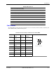


Specifications
June 2004 © 2004 Foundry Networks, Inc. A - 5
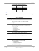
Cable Pinouts
The following tables provide cable pinout information for the console (RJ-45), Ethernet (RJ-45), T1(RJ-48C), and
modem (DB-9 to DB-9) or (DB-25 to DB-9) cables.
HDLC
Frame Relay
Multilink Frame Relay (MFR)
FRF.15 (End-to-End)
FRF.16 (UNNI/NNI)
Management Interfaces
Console: RJ-45
AUX: DB-9
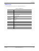
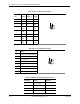
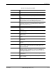
Table A.7: Pinouts: Foundry-to-Terminal Console Cable (DB-9)
Foundry
DCE Pin Signal Direction
Workstation
DTE Pin
1 data carrier
detect
<— 1
2 transmit data —> 2
3 receive data <— 3
4 data terminal
ready
—> 4
5 signal ground <—> 5
6 data set ready <— 6
7 request to
send
—> 7
8 clear to send <— 8
9 not used 9
Table A.6: Miscellaneous
Service Levels and Connectivity
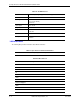
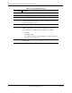
Pin 5
Pin 1
Pin 9
Pin 6
RS-232 DCE on DB-9 Female