Foundry AR-Series AR1202 and AR1204 Installation Guide 2100 Gold Street P.O. Box 649100 San Jose, CA 95164-9100 Tel 408.586.1700 Fax 408.586.
Copyright © 2004 Foundry Networks, Inc. All rights reserved. No part of this work may be reproduced in any form or by any means – graphic, electronic or mechanical, including photocopying, recording, taping or storage in an information retrieval system – without prior written permission of the copyright owner. The trademarks, logos and service marks (“Marks”) displayed herein are the property of Foundry or other third parties.
Contents CHAPTER 1 GETTING STARTED...................................................................................... 1-1 INTRODUCTION ...........................................................................................................................................1-1 AUDIENCE ..................................................................................................................................................1-1 NOMENCLATURE ..........................................................
Foundry AR-Series AR1202 and AR1204 Installation Guide POWER REQUIREMENTS .......................................................................................................................3-2 NETWORK CONNECTION .......................................................................................................................3-2 CABLES REQUIRED ...............................................................................................................................3-2 TOOLS REQUIRED ..........
Contents APPENDIX B TROUBLESHOOTING ....................................................................................B-1 ALARMS AND SYSTEM STATUS .................................................................................................................. B-1 WAN STATISTICS ..................................................................................................................................... B-1 NETWORK TESTS ............................................................................
Foundry AR-Series AR1202 and AR1204 Installation Guide vi © 2004 Foundry Networks, Inc.
Chapter 1 Getting Started Introduction This guide describes how to install and configure the AR1202, AR1202E, AR1204, and AR1204E router. Audience This manual is designed for system administrators with a working knowledge of Layer 2 and Layer 3 switching and routing. If you are using a Foundry Layer 3 Switch, you should be familiar with the following protocols if applicable to your network – IP, RIP, OSPF, BGP4, PIM, and VRRP.
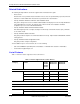
Foundry AR-Series AR1202 and AR1204 Installation Guide Related Publications The following Foundry Networks documents supplement the information in this guide. • Release Notes Printed release notes provide the latest information. If release notes are provided with your product, follow the instructions contained within them instead of those provided in other documentation.
Getting Started Table 1.
Foundry AR-Series AR1202 and AR1204 Installation Guide Table 1.
Getting Started Table 1.1: Feature Supported in AccessIron Devices (Continued) Category Feature AR1202 AR1204 AR1208 AR1216 AR3201-T-CL AR3202-T-CL AR3201-CH AR3202-CH Timed Access List How to Get Help Foundry Networks technical support will ensure that the fast and easy access that you have come to expect from your Foundry Networks products will be maintained. Web Access • http://www.foundrynetworks.
Foundry AR-Series AR1202 and AR1204 Installation Guide 1-6 © 2004 Foundry Networks, Inc.
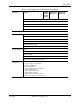
Chapter 2 Product Introduction This chapter provides information about the Foundry AR1202 and AR1204 router front and back panels, LEDs, cable connection ports, and panel components. Overview This section describes front- and back-panel components of the Foundry AR1202 and AR1204 router. Additional information is also provided in following sections about external cables, wiring, and connection points.
Foundry AR-Series AR1202 and AR1204 Installation Guide Figure 2.2 AR1202 Router Back Panel WAN Ports 1 - 2 Fast Ethernet Port 0 Fast Ethernet Port 1 AUX Port Console Port 12 VDC Input Jack LEDs The AR1202 front-panel LEDs indicate real-time unit status. Table 2.1provides information about how to interpret the LED states. Table 2.
Product Introduction Table 2.2: AR1202 Back-Panel Ports Connector Description WAN 1 - WAN 2 WAN connection ports. These ports accept cables with RJ-48C connectors. FE 0 / 1 Ethernet LAN connection ports. These ports accept cables with RJ-45 cable connectors. AUX Reverse telnet connection. This port accepts a cable with a male DB-9 connector. Console Console management port. This port accepts a cable with an RJ-45 cable connector. DC power 12 VDC power connection. This port accepts the 2 mm.
Foundry AR-Series AR1202 and AR1204 Installation Guide Figure 2.4 AR1204 Router Back Panel WAN Ports 1 - 4 Fast Ethernet Port 0 Fast Ethernet Port 1 AUX Port Console Port 12 VDC Input Jack LEDs The AR1204 front-panel LEDs indicate real-time unit status. Table 2.3provides information about how to interpret the LED states. Table 2.
Product Introduction Table 2.4: AR1204 Back-Panel Ports June 2004 Connector Description WAN 1 - WAN 4 WAN connection port. These ports accept cables with RJ-48C connectors. If drop and insert is configured, then ports 1 and 2 are reserved for that feature. FE 0 - FE 1 Ethernet LAN connection ports. These ports accept cables with RJ-45 cable connectors. AUX Reverse telnet connection. This port accepts a cable with a male DB-9 connector. Console Console management port.
Foundry AR-Series AR1202 and AR1204 Installation Guide 2-6 © 2004 Foundry Networks, Inc.
Chapter 3 Installation This chapter describes how to install and prepare the Foundry AR1202 and AR1204 router for operation. Information is also provided describing the system front and back panels, operator interface, how to mount the chassis, and how to connect network and power cables. Before you install the AR1202 and AR1204, familiarize yourself with the network interface and power connections described in this chapter.
Foundry AR-Series AR1202 and AR1204 Installation Guide Power Requirements The AR1202 and AR1204 router operates on 12 VDC power. A 12 VDC power supply and an AC power cord are shipped with the router. Network Connection To successfully complete the installation, the router must be connected to a network. Before you start the installation, make sure that a live network connection is available at the installation site. Cables Required The AR1202 and AR1204 router ships with a Console cable.
Installation Unpacking and Inspecting After opening the shipping carton, remove and save all packing materials and boxes. NOTE: Save the packing materials. If you need to return the product, you will need to repack the unit with the original packing material. Check the packing slip and contents of the shipping carton to ensure that you have received the following items. Figure 3.
Foundry AR-Series AR1202 and AR1204 Installation Guide Wall-Mounting Option An optional wall-mounting assembly is available for mounting the AR1202 and AR1204 router on a vertical surface. The wall-mount components are shipped in the same box with the AR1202 and AR1204 router, and are shown in the following figure: Figure 3.6 Wall-Mount Components Wall-mount bracket Power supply strap Router to wall-mount bracket screws: (4) 4-40 x .
Installation Figure 3.7 Rack-Mount Components (2) Rack Carriage Assemblies Rack Tray 2) Mounting Brackets (4) Velcro Tie Wraps 4) 10-24 x .5 Phillips Pan Head Screws for Equipment Rack (4) 10-24 x .5 Phillips Pan Head Screws for Equipment Rack (2 sets) Velcro Mounting Pads (6) 6-32 x .25 Phillips Flat Head Mounting Bracket Screws 4) 4-40 x .
Foundry AR-Series AR1202 and AR1204 Installation Guide Figure 3.8 Table Top Installation 110/120 VAC Outlet Threaded Hole 12 VDC Port Cable Retainer 1. Place the unit on the table surface. 2. Insert the DC power cable into the DC input jack on the front of the unit. 3. Attach the cable retainer bracket behind the molded strain relief on the power supply cable near the DC input jack. 4.
Installation Ensure that the router is oriented in a manner that allows the LEDs to be visible. 2. Attach the assembly with the mounted router to the wall surface with four (provided) 6 x 1 inch Phillips pan head screws and hollow wall plastic anchors. NOTE: The provided hollow wall anchors are not designed for installation in hard walls. These anchors should only be installed in a sheet rock (gypsum wall board) wall. 3.
Foundry AR-Series AR1202 and AR1204 Installation Guide 8. Engage and tighten the captive screw on the cable retainer bracket in the threaded hole adjacent to the DC input jack on the router. 9. Coil the excess cable and secure it on the tray behind the router. 10. Mount the tray in the equipment rack using either four (provided) Phillips pan head 10-24 x .5 inch screws or four (provided) Phillips pan head 12-32 x .5 inch screws, whichever fits the equipment rack. 11.
Installation 2. Insert the RJ-48C connectors on the other ends of the cables in the WAN ports on the front panel of the Foundry router. Make sure that the cable connectors are locked and secure in the ports. See Table A.9 on page A-6 for pinout information about this cable. Figure 3.12 Connecting the WAN Cable Connect to Service Provider’s Demarcation Point WAN Port 1 Connecting Drop and Insert Cables WAN ports 1 and 2 can alternatively be used for drop and insert traffic.
Foundry AR-Series AR1202 and AR1204 Installation Guide 1. Connect the RJ-45 Console cable to the Console port on the router. 2. Connect the other end of the RJ-45 Console cable to the RJ-45 end of the adapter. 3. Connect the DB-9 end on the adapter to the management terminal or workstation. Figure 3.
Chapter 4 Configuration This chapter describes how to login; change the default password, configure the router and users, and change the factory default configuration. The boot process and software upgrade process is also discussed in detail. Logging In If you have not established a local console connection, see “Operator Interface” on page 3-9 for more information. The following figure shows the login sequence and the initial prompt after login is complete. Figure 4.
Foundry AR-Series AR1202 and AR1204 Installation Guide Ethernet Configuration Tip To avoid Ethernet mismatch problems, the AR1202 and AR1204 router and the network device to which it is attached should both be configured identically for speed and duplex. For example, if the router is configured for auto-negotiation and the far end is configured manually, the router detects the speed, but defaults to half-duplex mode.
Configuration NOTE: Changing the administrator login name does not change the administrator’s password. Use the password procedure to change the password. System Host Name Use the configure hostname command to assign a host name to the Foundry router. Once assigned, the host name becomes the command line interface (CLI) prompt name. To configure the host name: 1. Access the terminal configuration mode: Foundry-AR1204# configure term 2. Type hostname, and then type a new host name. 3. Press Return.
Foundry AR-Series AR1202 and AR1204 Installation Guide example: Foundry-AR1204/configure# user John level 2 The system prompts you to enter a new password. 3. Enter the new password. The system prompts you to re-enter the new password. 4. Re-enter the new password. The system confirms that the password is set and confirms the name of the added user. You can use the display user_accounts command to view user information.
Configuration Table 4.1: Default Configuration Values Parameter Default speed auto (negotiates 10 Mbps or 100 Mbps) address uses the current address stored in the system.cfg file (if one exists), otherwise an IP address must be configured from the command line interface duplex auto (negotiates half-duplex or full-duplex) Table 4.
Foundry AR-Series AR1202 and AR1204 Installation Guide Table 4.4: E1 Interface Default Configuration Parameter Default Value Optional Values framing crc non-crc disabled linecode HDB3 no optional value clock_source internal line linemode short_haul long_haul jitter enabled disabled lbo 43 db 12 db yellow_alarm generate and detect no optional value Table 4.
Configuration host/configures interface drop_insert Foundry mode 2 1 Note that “2” represents port 2. This is the only value that will be accepted. The “1” represents the mode (data and voice) for which port 2 is configured. Display interface drop_insert Foundry host# show interface drop_insert Foundry drop_insert Foundry ----------------------- number of links 0 Configure the link The default value for timeslots is all (available).
Foundry AR-Series AR1202 and AR1204 Installation Guide Display interface drop_insert Foundry host# show interface drop_insert Foundry drop_insert Foundry ----------------------- number of links 2 Interface Mode: DATA AND VOICE MODE Signaling Type: RBS Switching Routing/IPMUX Modes To switch between IPMux and dynamic routing modes, a valid software license must be installed on the AR1202 and AR1204 router. Contact Foundry and provide the serial number for the router.
Configuration A software upgrade consists of two files: AR01_#### and T1000.bin. The .Z file is the operating system for the Foundry system; the .bin file contains the downloadable boot images. NOTE: Foundry systems do not support two simultaneous downloads. NOTE: Refer to the appropriate Command Reference Guide (domestic or international products) for specific command parameters, options, and context.
Foundry AR-Series AR1202 and AR1204 Installation Guide Booting From a Network TFTP Server In the rare and unlikely situation where a software version upgrade fails, a network boot may be performed as described in the following procedure. 1. Assume that the new AR01_#### download failed when the following command was issued: Router# file download 192.168.10.1 tftpdir/8.0/AR01_#### This command line is appropriate when the new upgrade AR01_#### file resides on a tftp server host with IP address 192.168.10.
Configuration The following text is output to the terminal: host name : host 10. To keep this parameter, press the Enter key. The following text is output to the terminal: file name : /flash1/T2000.Z 11. Enter the path-qualified file name: type /tftpdir/r4.6/AR01_#### (or whatever is consistent with the file download command in the above example) and press the Enter key. The following text is output to the terminal: 1net on ethernet [e] : 10.1.0.1:fff0000 12.
Foundry AR-Series AR1202 and AR1204 Installation Guide The following text is output to the terminal: flags [f] : Ox8a Set the target name. Press the Enter key. The following text is output to the terminal: target name [tn] :T1200 The name that you use to configure the Foundry router will become the system prompt. Ensure that the startup script parameter is blank. The “other” parameter may be blank or left as “inPci.
Appendix A Specifications This appendix includes technical information about the operating environment, power application, interfaces, cable pinouts, MIBs, and physical cables and adapters used to connect the Foundry AR1202 and AR1204 router to a network. System Specifications The following tables provide various technical specifications for the Foundry AR1202 and AR1204 router. Table A.
Foundry AR-Series AR1202 and AR1204 Installation Guide Table A.1: Environment, Hardware, Memory, and Power Frequency range 50 to 60 Hz Nominal voltage range 100 to 240 V RMS Average power consumption 15 watts DC Power Voltage range +12 VDC Average power consumption 11.52 watts Table A.2: Performance Monitoring Statistics Storage Statistics for the last 24 hours in 15-minute increments Statistics for 24-hour increments Reporting G.
Specifications WAN Interfaces The following tables provide specifications for T1 WAN and E1 WAN interfaces. Table A.3: T1 WAN Interface Receive line rate 1.544 Mbps ± 32 ppm Line code b8zs or ami Framing d4 or esf Interface ESF FDL AT&T TR-54016-1986 AT&T TR-54016-1989 ANSI T1.403-1989 June 2004 Input signal DSX-1 0 to – 24 db Output signal 0 – 7.5 db – 15 db Equalization 0 to 655 ft.
Foundry AR-Series AR1202 and AR1204 Installation Guide Table A.4: E1 WAN Interface Receive line rate 2.048 Mbps ± 50 ppm (payload = 1.984 Mbps) Line code HDB3 Framing crc non-crc (ITU G.704) unframed Input signal 0 to -32 db Output signal ITUG.703 Impedance 75 ohm 120 ohm Connectors RJ-48C Timing internal network LAN Interfaces The following table provides information about Ethernet interface. Table A.5: Specifications: Ethernet LAN Interface Two 10/100 Base-T, 802.
Specifications Table A.6: Miscellaneous Service Levels and Connectivity HDLC Frame Relay Multilink Frame Relay (MFR) FRF.15 (End-to-End) FRF.16 (UNNI/NNI) Management Interfaces Console: RJ-45 AUX: DB-9 Cable Pinouts The following tables provide cable pinout information for the console (RJ-45), Ethernet (RJ-45), T1(RJ-48C), and modem (DB-9 to DB-9) or (DB-25 to DB-9) cables. Table A.
Foundry AR-Series AR1202 and AR1204 Installation Guide Table A.8: Pinouts: Ethernet Cable (RJ-45) Foundry Pin Signal Direction LAN Signal 1 TxD+ —> TxD+ 2 TxD– —> TxD– 3 RxD+ <— RxD+ 4 not used not used 5 not used not used 6 RxD– 7 not used not used 8 not used not used <— Pin 8 Pin 1 RxD– Table A.
Specifications Table A.10: DB-25 to RJ-45 Modem Adapter Pinouts RJ-45 Pin Signal DB-25 Pin 5 Ground 7 6 TxD 2 7 no connection - 8 no connection - MIBs Foundry systems support standard and enterprise MIBs. The following tables provide information about supported MIBs. Table A.11: Standard MIBS Standard MIB Description RFC 1213 Standard MIB-II objects. The following groups or variables are not supported for this MIB: RFC 1315 • egp • at MIB objects for frame relay DTE interface.
Foundry AR-Series AR1202 and AR1204 Installation Guide Table A.11: Standard MIBS (Continued) Standard MIB Description RFC 1657 Describes MIB objects used for BGP4 routing protocol. RFC 1724 Describes MIB objects used for RIP routing protocol. RFC 1850 Describes MIB objects used for OSPF routing protocol. RFC 1997 Facilitates and simplifies the control of routing information. This rfc suggests a grouping of destinations so that the routing decision can also be based on the identity of a group.
Specifications Table A.12: Foundry Enterprise MIBs June 2004 Foundry MIB Description bundle.mib Defines objects related to bundle and link configuration. chassis.mib Defines objects related to chassis serial number and model number. config.mib Defines objects related to saving configurations for network and flash. dsx-tc.mib Defines textual conventions for DSX MIBs. This MIB should be compiled before any other DSX MIBs.
Foundry AR-Series AR1202 and AR1204 Installation Guide A - 10 © 2004 Foundry Networks, Inc.
Appendix B Troubleshooting This chapter provides general troubleshooting tips in addition to network tests and diagnostics information for the Foundry AR1202 and AR1204 router. Alarms and System Status The AR1202 and AR1204 router reports various alarms upon detecting certain irregular conditions in the incoming WAN signals. For more information about the command line interface and system commands, refer to the appropriate Foundry Command Reference Guide (either the domestic or international version).
Foundry AR-Series AR1202 and AR1204 Installation Guide Network Tests If the system is not working correctly after verifying that the cabling is correct between the Foundry router and the external network equipment, run these basic tests to isolate the problem to the LAN port, WAN link, or serial interface ports. Ping Test The Ping test checks connectivity between the Foundry system and another host system on the LAN.
Troubleshooting Diagnostics Tips The information in the following tables may help to isolate or resolve certain system problems. General Symptoms The following table provides general diagnostics information that applies the AR1202 and AR1204 router. Table B.2: Common Symptoms and Actions Symptom Cause Action Power LED does not illuminate with power applied. No power is applied. 1 Verify that the AC power cord is functional. 2 Make sure the power supply is working properly.
Foundry AR-Series AR1202 and AR1204 Installation Guide Table B.2: Common Symptoms and Actions (Continued) Symptom Cause Action WAN Status LED is not illuminated. The link is not in service Enable the link using the appropriate derivative of the configure module t1 enable command. WAN Status LED is red. The link is faulty. (The system has detected an abnormal incoming signal.) If a LOS (loss of signal) alarm is present: 1 Check the WAN cable connections to the system.
Troubleshooting Table B.2: Common Symptoms and Actions (Continued) Symptom Cause Action System fails to boot, and stops at [Foundry Boot]. 1 AR01_#### file is non-existent or has become corrupt 1 Connect your terminal to the Console port on the Foundry router. 2 Flash is corrupt. 3 Power cycle the Foundry router continuously by pressing the Enter key until you see the following prompt: 2 Configure the modem for 9600/8/None, and no flow control. [Foundry Boot] 4 Type c, and press Enter.
Foundry AR-Series AR1202 and AR1204 Installation Guide B-6 © 2004 Foundry Networks, Inc.