
Troubleshooting guide


2-5. UPS installation for parallel systems
Option 4:
After connecting N1&L2, it becomes three outputs, one high-voltage output (208/220/230/240V) at L1-N2 and two low-
voltage outputs (104/110/115/120V) at L1-N1 & L2-N2. However, there is a limit for current rating at L1-N1 & L2-N2: 25A
for 6Kmodel and 42A at 10K model. You must connect the load taking into account such limits. Please read the notes
before installation.
Connect the low-voltage load to L1-N1 and L2-N2, and connect the high-voltage load to L1-N2.
Note1: If any load current in L1-N1 or L2-N2 is higher than 25A in 6K model and 42A in 10Kmodel, the UPS will still
operate normally without overload warning because the total load is under the specified limit. However, the high current
can damage the isolation transformer due to overheat caused by the high current. Hence, the installation must be done
with a technician to ensure that the load current will not exceed this limitation.
Note 2: When connecting to low-voltage and high-voltage at the same time as described in option 4, the L1-N1 & L2-N2
will feed low-voltage loads in non-isolated status because high-voltage is being generated by shorting N1-L2. If keeping
a connected load in isolated status is required, we recommend that you may only use two low-voltages at L1-N1 or L2-N2
like illustrated in option 1, and also make sure that the total current in L1-N1 or L2-N2 does not exceed the value specified
in Note1.
If the UPS is only available for single operation, you may skip this section to the next.
1) Install wiring as instructed in the UPS installation section.
2) Connect the output wires of each UPS to an output breaker.
3) Connect all output breakers to a major output breaker. The major output breaker will then directly connect to the loads.
4) Each UPS must be connected to an independent battery pack.
Note: The parallel system cannot run on a single battery pack. Otherwise, it may cause system permanent failure.
5) Remove the cover of the parallel current cable port on the UPS. Connect each UPS one by one with the parallel cable
and share current cable. Reattach the cover.
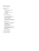
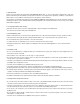
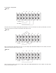
6) Refer to the following wiring diagrams:
To Load 2
To Load 1
L 1
N1
L 2
N2
L
N
To Load 3