
Troubleshooting guide


6K 6K/10K
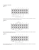
Diagram 1: Rear Panel Overview
2-3. Single UPS installation
Diagram 2: Input/Output Terminal
1. RS-232 communication port
2. USB communication port
3. Emergency power off (EPO) connector
4. Parallel connection port
5. Parallel port intelligent slot
6. Charger fan
7. Power stage fan
8. Maintenance bypass switch
9. Input circuit breaker
10. Isolation transformer fan
11. Input/Output terminal (Refer to diagram 2 for details)
12. Output terminal 1
13. Output terminal 2
14. Utility input terminal
15. Non-isolated neutral terminal.
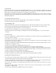
Installation and wiring must be performed by qualified personnel, and in accordance with the local electrical regulations
and codes. Also, you must observe the following instructions:
1) Make sure the mains wire and breakers in the building are enough for the rated capacity of the UPS to avoid the hazards
of electric shock or fire.
Note: Do not use a wall receptacle as the input power source for the UPS, as its rated current is less than the UPS
maximum input current. Failure to do so may result in a broken or burned out receptacle.
2) For safety considerations, turn off the mains switch in the building before installation.
3) Turn off all the devices before connecting them to the UPS.
4) Wiring sizes should be installed in accordance with the following table:
Wiring specification (AWG)
Model
Input Battery GroundOutput
Non-isolated
Neutral
6K
10K
10
8
10
8
10
8
10
8