
User's Manual
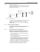

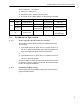

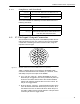


Table Of Contents

ES820 Hardware Guide: Specifications
12
4.3 3-Pin DC Input Connector
The Mesh Point uses a 3-pin connector to input power.
Figure 4.2. D38999/26FA9-98SN 3-pin Power Connector Pins
Table 4.2 shows the power connector pin-outs.
21
Enet1 Link/Act LED Out LED1, active Lo (8mA @2V diode)
22
RF Kill_n (Toggle) In SW1, RFKILL, active Lo
23
Reset_n (PB) In SW3, Reset, active on falling edge
24
Blackout_n (Toggle) In SW5, Blackout, active Lo
25
Enet2 D+ - Enet 2- RJ45 pin 8 Cat5 twisted pair4
26
Enet2 RX+ In Enet 2- RJ45 pin 3 Cat5 twisted pair2
27
Enet2 C+ - Enet 2- RJ45 pin 4 Cat5 twisted pair3
28
Enet1 D+ - Enet 1- RJ45 pin 8 Cat5 twisted pair4
29
Enet1 C- - Enet 1- RJ45 pin 5 Cat5 twisted pair3
30
Enet1 TX+ Out Enet 1- RJ45 pin 1 Cat5 twisted pair1
31
COM RXD In COM, RS232 Rcv (Monitor Port)
32
Zeroize (PB) In SW2, Zeroize, active on rising edge
33
Power_n (Toggle) In SW4, Power on, active Lo
34
Enet2 C- - Enet 2- RJ45 pin 5 Cat5 twisted pair3
35
GND - Ground
36
Enet1 C+ - Enet 1- RJ45 pin 4 Cat5 twisted pair3
37
GND - Ground
Table 4.1. ES820 37-Pin I/O Connector Pin-Outs
pin signal dir description
C
A
B
Table 4.2. ES820 DC Power Connector Pin-Outs
pin signal
A
+10 to 30 VDC
B
N/C
C
GND