
User Guide

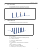

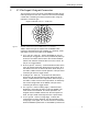


Table Of Contents

ES820 Bridge: Hardware
3
5 37-Pin Input/Output Connector
The connector on the rear panel of the ES820 provides all non-
radio input/output for the unit. In order to connect to the ES820,
a cable with a matching connector must be made, using the
required to connector type:
Amphenol MILDTL-D38999 / 26MD35PN
Figure 3. MIL-DTL-38999 Series III TV Shell/Insert 15-35 (socket)
Table 1 defines the pin-out required for the ES820 cable
connector. Most definitions are standard (ex., Ethernet, serial,
and USB). Five pins are unique to the ES820:
Power (pin 33 - active lo) - powers the ES820 on and off.
When this pin is toggled lo, the unit is permitted to power up
and boot. The switch state is tied to the chassis ON/OFF
switch: both switches must be OFF to turn the unit off. Tie
this pin to a toggle switch.
Blackout (pin 24 - active lo) - controls blackout mode, which
turns all chassis LEDs OFF. When this pin is held lo, all of
the LEDs on the box are dark at all times. When the pin is
not held lo, LEDs revert to normal operation. This pin would
commonly be tied to a toggle switch.
RF Kill (pin 22 - active lo) - controls the RF Kill feature,
which turns all radio transmission OFF. When this pin is
held lo, all RF emissions are suppressed. When the pin is
not held lo, radios revert to normal operation, as defined by
the current configuration of the ES820. This pin would
commonly be tied to a toggle switch.
Reset (pin 23 - active on falling edge) - reboots the box.
Resetting is equivalent to power cycling the ES820. The
reset function is immediate: all current operations are
stopped and the ES820 restarts from the initial power-on
state. This pin would commonly be tied to a push button.
Zeroize (pin 32 - active on rising edge) - restores the
configuration to factory defaults. This pin activates on the
rising edge of the signal. The zeroize function is immediate
when the ES820 is powered on. If the ES820 is powered off
1
21
31
11