
User's Manual

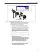
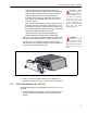

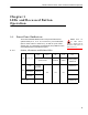


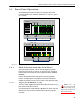

Table Of Contents

ES520 Hardware Guide: LEDs and Recessed Button Operation
21
3.1.2 Radio LEDs
The Mesh Point’s internal radios are each associated with a
pair of front-panel LEDs, labeled
Radio1 and Radio2. Radio
LEDs are arranged one above the other. Each radio then has
an associated upper and lower LED.
When the Mesh Point’s Received Signal Strength Indicator
(RSSI) feature (refer to the
Software GUI Guide) is Disabled (the
default),
Radio1 and Radio2 LEDs behave as shown below.
The upper LED can exhibit:
solid green - The associated radio is on.
intermittent green flash - The radio is passing traffic.
off - The associated radio is off or RF Kill is activated.
The lower radio LEDs are reserved for future functions on the
Mesh Point.
3.1.3 Port and Power LEDs
The Mesh Point’s front-panel Ethernet ports, including the WAN
and internal LAN switch ports, numbered
1 through 8 on the
front panel, are equipped with a link/activity LED. LAN switch
ports also feature a Power over Ethernet (PoE) status LED.
NOTE: The LEDs
for the Mesh
Point’s
Console port are
not operational.
The Mesh Point’s PSE function enables it to supply PoE to
Powered Devices (PDs) connected to its internal LAN switch
ports. The PoE status LED applies only when you have
connected PDs to the Mesh Point’s internal LAN switch
(Section 2.1.4) and only to ports on which the PSE (Power
Sourcing Equipment) function has been enabled (see the
Software GUI Guide).
Lnk/Act
can exhibit:
solid green - A link has been established for the port.
intermittent green flash - Traffic is passing on the link.
POE
can exhibit:
solid green - Power on: the port is supplying power to a
connected PD.