
User's Manual

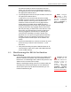


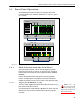

Table Of Contents

ES520 Hardware Guide: Installation
16
Figure 2.3. Installing the RJ-45 Connector Boot Assembly
1 Install the RJ-45 connector boot assembly on the end of the
cable that you will be plugging into the Fortress Mesh
Point’s WAN port, as shown in Figure 2.3:
If the RJ-45 connector is equipped with a molded
plastic boot, remove it from the connector. (Some
Ethernet cable connectors have a molded plastic outer
casing that is not designed for removal. This style of
connector is incompatible with the connector boot.)
Slide the compression nut, with the threaded opening
facing toward the connector, over the connector and
onto the cable.
Slide the compression bushing over the connector and
onto the cable.
Slide the threaded coupler, with the flanged end facing
toward the compression nut and bushing, over the
connector and onto the cable.
With the smooth-side prongs on the two halves of the
connector collar facing out and aligned with the RJ-45
connector’s locking tab, fit the collar around the
connector so that the connector’s locking tab is
compressed (the contact end of the connector extends
approximately 1/2" from the collar). Fit the outer tabs on
one half of the connector collar into the slots of the
other, and squeeze the two halves of the connector
collar together until they snap into place.
compression nut
compression
bushing
threaded
coupler
connector
collar
connector
boot
RJ-45 connector
RJ-45 connector locking tab
Ethernet cable
Boot/Connector Alignment
locking tab (on RJ-45 connector)
primary key tab (on boot inner ring)
Connector Boot Assembly