
User's Manual


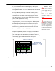
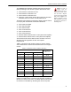


Table Of Contents

ES520 Hardware Guide: Installation
13
2.1.5 Port Locations
The ES520 Mesh Point’s dual antenna ports and grounding
stud are located on the back panel. The rest of the ES520’s
ports are located on the front panel, shown below.
Figure 2.2. Fortress ES520 Mesh Point Port Locations
2.1.6 Network Interfaces
The ES520 Mesh Point's Ethernet WAN port and eight LAN
switch ports, numbered
1–8, comprise its wired network
connections. Its two internal radios can be configured with up
to four independent wireless interfaces, or Basic Service Sets
(BSSs), each. You can configure the Mesh Point's network
interfaces to meet various deployment and security
requirements (see the
Software GUI Guide).
2.2 Connecting the ES520
The ES520 can be connected temporarily for preconfiguration
of the Mesh Point software and then permanently for
deployment.
+48V
DC
+48V
DC
Stat1
Stat2
Clr
Fail
Radio2
Radio1
Console
USB A/B
15
2
73
468
SW1 ResetSW2
Lnk/Act P OE
Lnk/
Act
Pwr
WAN
ES520
DC power input
WAN port, default encrypted
PD/PoE interface
RJ-45 serial port
RJ-45 Ethernet ports, default clear
PSE/PoE interfaces
USB
port
48V
DC
St1 St2
Clr
Fail
1
Radio
Console
USB
1
2
73
468
SW2
ResetSW1
Link/Act POE
Link/
Act
Pwr
WAN
Serial
2
12/24V 48V
ES520
5
RJ-45 serial ports
weathertight multi-mode DC power input
USB ports
DC power input
ES520
version 2
ES520
version 1
rear-panels:
two N-type antenna ports;
one grounding stud
ANT1 ANT2
+
-