
User's Manual


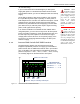


Table Of Contents

ES520 Hardware Guide: Installation
12
required by the new PD’s Class (as described above), the new
PD will not be powered up.
NOTE: If one port
in a PSE pair is
supplying power to a
PoE Class 3 or Class 0
device, you can ensure
that their shared fuse
will not be overloaded
by an attempt to supply
power to another PD by
leaving PSE
Disabled
(the default) on the sec-
ond port in the pair.
In addition to the overall maximums, keep in mind that the
distribution of PDs across LAN switch interfaces must not
exceed the 16-Watt limit per vertically stacked port-pair
(described above). A given pair of ports can therefore supply
sufficient power to only one Class 3 or Class 0 PD or to two
Class 2 and/or Class 1 PDs.
Each associated (vertically aligned) pair of PoE LAN switch
interfaces shares a self-recovering fuse. If you exceed the 16-
Watt port-pair maximum without exceeding the overall
maximum, the breaker will trip, temporarily powering both ports
off. The circuit resets automatically, re-enabling both ports. If
the PSE overload has not been corrected, however, the circuit
will break again. The process will recycle until one of the PDs
on the pair is unplugged.
In order for the Mesh Point to supply PoE to PDs through a
LAN switch port, you must enable PSE on the port, as
described in the
Software GUI Guide.