
User's Manual
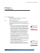
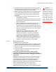


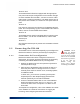

Table Of Contents

ES2440 Hardware Guide: Installation
7
The ES2440 Mesh Point’s Serial port and three Ethernet ports,
Ethernet1/WAN/POE, Ethernet2, and Ethernet3 are located on
the front panel, along with the
DC Power inlet and recessed
Reset button (see Figure 2.1).
All ES2440 front-panel ports are protected by captive covers.
Unused ports should remain covered to protect against dust
and other debris. Covered or uncovered, all ES2440 ports are
waterproof.
The recessed button used to restore the running configuration
to factory defaults (Section 3.2) is also located on the front
panel, beneath a protective screw cap.
The LEDs located above the ES2440’s ports are described in
Section 3.1
2.1.3.2 Grounding Stud
On all ES2440 models, the grounding stud is the wing nut
located on the left rear corner of the chassis, viewing the
ES2440 from the front as shown in Figure 2.1 (refer to also to
Figure 2.2).
2.1.3.3 Rear Panel Connectors
The ES2440 rear-panel antenna port configuration depends on
the Mesh Point’s hardware model.
ES2440-3555
Nine antenna connectors are situated on the ES2440-3555
back panel: eight, corresponding by pair to the ES2440’s four
internal radios, as shown below, and one for the ES2440
internal GPS.
Figure 2.2. ES2440-3555 Back-Panel Antenna Connectors
Antenna port ring labels identify which radio uses to each pair
of ports by color: red, yellow, blue and brown (right-to-left in
Figure 2.2), correspond to radios 1, 2, 3, and 4, respectively.
Solid ring labels identify the radios’
A antenna ports; dashed-
line labels identify
B ports. Antenna port labels are printed with
the corresponding radio’s 802.11 capabilities:
802.11a/b/g/n or
802.11a/n.
antenna ports B
GPS antenna port
antenna ports A
Radio 4
Radio 3 Radio 2 Radio 1
grounding stud