ES2440 High-Capacity Infrastructure Mesh Point Hardware Guide www.gdfortress.com © 2012 Fortress Technologies, Inc.
ES2440 Hardware Guide Fortress ES2440 High-Capacity Infrastructure Mesh Point [rev.4a] 009-00045-00r4 Copyright © 2012 Fortress Technologies, Inc. All rights reserved. This document contains proprietary information protected by copyright.
ES2440 Hardware Guide transit, or (e) has not been installed, operated, repaired or maintained in accordance with instructions provided by Fortress. Purchaser is responsible for all freight expenses incurred as a result of returning Products that are determined by Fortress to be (1) free from defect or (2) defective as a result of one of the circumstances listed in (a) through (e) above. Such Products shall be shipped back to Purchaser, and Purchaser shall be responsible for associated freight charges.
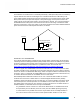
ES2440 Hardware Guide IMPORTANT SAFETY INFORMATION The ES2440 is an outdoor device. It should be powered by a mid-span PoE (Power over Ethernet) injector obtained from Fortress Technologies over a weatherized Ethernet cable OR by a DC power adapter/supply obtained from Fortress Technologies over a weatherized DC power cable. Either power source, mid-span PoE injector or DC power supply, and the power cord and AC supply it plugs into should remain indoors, protected from the weather.
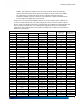
ES2440 Hardware Guide TDWRs. This requirement applies even if the master is outside the 35 km radius but communicates with outdoor clients which may be within the 35 km radius of the TDWRs. The requirement for ensuring 30 MHz frequency separation is based on the best information available to date. If interference is not eliminated, a distance limitation based on line-of-sight from TDWR will need to be used. Please refer to the original KDB 443999 as posted on the FCC web site for the complete text.
ES2440 Hardware Guide TDWR Location Information LONGITUDE LATITUDE FREQUENCY TERRAIN ELEVATION (MSL) [ft] AERO.
ES2440 Hardware Guide HARMFUL INTERFERENCE TO RADIO OR TELEVISION RECEPTION, WHICH CAN BE DETERMINED BY TURNING THE EQUIPMENT OFF AND ON, THE USER IS ENCOURAGED TO TRY TO CORRECT THE INTERFERENCE BY ONE OR MORE OF THE FOLLOWING MEASURES: • REORIENT OR RELOCATE THE RECEIVING ANTENNA. • INCREASE THE SEPARATION BETWEEN THE EQUIPMENT AND THE RECEIVER. • CONNECT THE EQUIPMENT INTO AN OUTLET ON A CIRCUIT DIFFERENT FROM THAT TO WHICH THE RECIEVER IS CONNECTED.
ES2440 Hardware Guide CAUTION: 4.4 GHZ RADIOS ARE OPTIONAL EQUIPMENT IN THE ES2440. THE 4.400 GHZ–4.780 GHZ FREQUENCY RANGE IS REGULATED BY THE UNITED STATES NATIONAL TELECOMMUNICATIONS AND INFORMATION ADMINISTRATION AND ALLOCATED EXCLUSIVELY FOR GOVERNMENT USE. USE OF 4.4 GHZ RADIOS OUTSIDE OF U.S. GOVERNMENT APPLICATIONS AND AUTHORITY IS STRICTLY FORBIDDEN.
ES2440 Hardware Guide: Table of Contents Table of Contents 1 Overview 1 This Document . . . . . . . . . . . . . . . . . . . . . . . . . . . . . . . . . . . . . . . . .1 Related Documents . . . . . . . . . . . . . . . . . . . . . . . . . . . . . . . . . . . . . . . . . . . 1 The ES2440 . . . . . . . . . . . . . . . . . . . . . . . . . . . . . . . . . . . . . . . . . . .2 Hardware Models . . . . . . . . . . . . . . . . . . . . . . . . . . . . . . . . . . . . . . . . . . . . .
ES2440 Hardware Guide: Table of Contents 3 LEDs and Button Operation 12 Front-Panel LED Indicators . . . . . . . . . . . . . . . . . . . . . . . . . . . . . . 12 Recessed Button Operation . . . . . . . . . . . . . . . . . . . . . . . . . . . . . . 13 4 Specifications 14 Hardware Specifications . . . . . . . . . . . . . . . . . . . . . . . . . . . . . . . . . 14 Physical Specifications . . . . . . . . . . . . . . . . . . . . . . . . . . . . . . . . . . . . . . . . 14 Environmental Specifications . . .
ES2440 Hardware Guide: Overview Chapter 1 Overview 1.1 This Document This user guide covers preparing and installing the Fortress ES2440 High-Capacity Infrastructure Mesh Point hardware. It also describes the LED indicators and recessed button operation and provides specifications. Other Fortress hardware devices are covered in separate hardware guides, one for each Mesh Point (or Network Encryptor) model. WARNING: can cause physical injury or death and/or severely damage your equipment.
ES2440 Hardware Guide: Overview 1.2 The ES2440 The ES2440 High-Capacity Infrastructure Mesh Point is a full-featured Fortress network device, providing strong data encryption and Multi-factor Authentication™, including native RADIUS authentication, to users and devices on the network it secures. Two ES2440 models are each equipped with four radios: Radio 1 is a 400 mW (milliwatt, peak power) dual-band 802.11a/b/g/n radio that can be configured to use either the 802.11b/g band or the 802.
ES2440 Hardware Guide: Overview The 4.400 GHz–4.780 GHz frequency range is regulated by the NTIA (National Telecommunications and Information Administration), the parent agency of the FCC (Federal Communications Commission). FCC labeling applied to the ES2440-3444 chassis therefore provides an FCC ID for only the 802.11a Radio 1. Each radio-equipped model is furnished with the appropriate rear-panel antenna port configuration for the number and type of radios installed.
ES2440 Hardware Guide: Installation Chapter 2 Installation 2.1 Preparation Before proceeding with installation, review the safety information in Section 2.1.1 below. 2.1.1 Safety Requirements To prevent damage to the product and ensure your personal safety, operate the Mesh Point only within the operating specifications given in Section 4.1.
ES2440 Hardware Guide: Installation 2.1.2 Grounding: Ground the ES2440 by connecting a ground wire to the grounding stud located on the left rear corner of the chassis (refer to Figures 2.1 and 2.2, below). Radio Frequency: The Mesh Point’s internal radios conform to the FCC’s safety standard for human exposure to RF electromagnetic energy, provided that you follow these guidelines: Do not touch or move the antennas while the unit is transmitting or receiving.
ES2440 Hardware Guide: Installation will automatically disconnect PoE if external DC power is applied and will only reconnect PoE when DC power is removed. When either PoE or external DC are removed, the ES2440 will reboot.
ES2440 Hardware Guide: Installation The ES2440 Mesh Point’s Serial port and three Ethernet ports, Ethernet1/WAN/POE, Ethernet2, and Ethernet3 are located on the front panel, along with the DC Power inlet and recessed Reset button (see Figure 2.1). All ES2440 front-panel ports are protected by captive covers. Unused ports should remain covered to protect against dust and other debris. Covered or uncovered, all ES2440 ports are waterproof.
ES2440 Hardware Guide: Installation ES2440-3444 The ES2440-3444 is likewise equipped with the appropriate rear-panel antenna port configuration for the number and type of radios installed: two for Radio 1, and one for each 4.4 GHz radio (Radio 2, Radio 3 and Radio 4). The GPS antenna port is also present in this model, for a total of six rear-panel antenna ports.
ES2440 Hardware Guide: Installation 2.2.2 Connections for Deployment Review the IMPORTANT SAFETY INFORMATION on page iii and Safety Requirements in Section 2.1.1 before installing or operating the ES2440. 2.2.2.1 Connecting the ES2440-3555 or ES2440-35 for Deployment Antennas used with the ES2440 must be professionally installed and must conform to FCC EIRP (Effective Isotropic Radiated Power) limitations. All antennas must have 50 Ohms impedance.
ES2440 Hardware Guide: Installation 7 Verify that the Power LED illuminates, as well as the corresponding LEDs for all connected ports and enabled radio(s). 2.2.2.2 Connecting the ES2440-3444 or ES2440-34 for Deployment Connection procedures for the ES2440-3444/34 are identical to those provided for the ES2440-3555 above, except that MIMO is not an option for its 4.4 GHz radios (Radio 2, and Radio 3 and Radio 4, if present).
ES2440 Hardware Guide: Installation 2.3 Mast Mounting the ES2440 A Mast-Mounting Kit is included with the ES2440-3555 and ES2440-3444. The ES2440-0 ships without it. Figure 2.3. Mast mounting the ES2440 Mast-mounting hardware accommodates masts from 1.5" to 3" in diameter. 1 Fit the two hex bolts through the center mounting holes along the ES2440's sides, top to bottom.
ES2440 Hardware Guide: LEDs and Button Operation Chapter 3 LEDs and Button Operation 3.1 Front-Panel LED Indicators The ES2440 Mesh Point features nine LEDs on the front panel (shown in Figure 2.1, on page 6). Power, Status and Ethernet LEDs are present on all three ES2440 hardware models, and their behaviors have the same meanings across all models. can exhibit: solid green - Mesh Point is powered on and operating normally. off - Mesh Point is powered off. slow-flash green - Mesh Point is booting.
ES2440 Hardware Guide: LEDs and Button Operation Table 3.1. LED Indicators in the ES2440 color green behavior Power Status Ethernet1, Ethernet2, Ethernet3 Link/Act solid normal operation - link established radio ON slow flash booting Auto-Config distribution - - intermittent - - passing traffic passing traffic powered OFF - - radio OFF or RF Kill enabled off Radio1, Radio2, Radio3, Radio4 a a. Present only on radio-equipped ES2440s, according to the number of radios installed.
ES2440 Hardware Guide: Specifications Chapter 4 Specifications 4.1 Hardware Specifications 4.1.1 Physical Specifications ES2440-3555/35 ES2440-3444/34 form factor: mountable, compact, rugged chassis dimensions: 2.75" H x 8.5” W x 10.75” D (6.99 cm x 21.59 cm x 27.3 cm) weight: power supply: 7.5 lbs (3.4 kg) / 7 lbs (3.18 kg) ES2440-0 6.5 lbs. (2.95 kg) 802.
ES2440 Hardware Guide: Specifications 4.1.2 Environmental Specifications ES2440-3555, ES2440-3444 ES2440-35, ES2440-34 ES2440-0 40 W 32 W 25 W 137 BTUs/hr 110 BTUs/hr 85 BTUs/hr maximum power draw: maximum heat dissipation: cooling: Convection Cooled operating temperature: -40º–158º F (-40º–70º C) operating relative humidity: 5%–95% (non-condensing) storage temperature: 4.1.
ES2440 Hardware Guide: Specifications Table 4.1 shows the serial port adapter pin-outs. Table 4.1. RJ45-to-DBP Adapter Pin-Outs 4.3 RJ45 pin DB9 pin standard color 1 8 grey 2 6 brown 3 2 yellow 4 5 green 5 - red 6 3 black 7 4 orange 8 7 blue 2-Pin DC Input Connector The ES2440 Mesh Point uses a 2-pin connector to input DC power. pin A pin B Figure 4.2. 2-pin Power Connector Pins Table 4.2 shows DC power connector pin-outs. Table 4.2.
ES2440 Hardware Guide: Index Index Numerics 4.4 GHz radios 802.
ES2440 Hardware Guide: Index R radios 2, 14 connecting antennas 7, 9 LEDs 12–13 precautions vii, 2, 9 safety requirements 5 specifications 14 RJ-45-to-DB9 adapter 15–16 S safety precautions iii, 1, 5, 8, requirements 4–5 see also specifications serial port adapter 15–16 location 7 specifications 14–15 9 T TDWR iii–v temperature 4, 15 V VDC input 7, 8, 9, 10, 14 connector pin-outs 16 vibration 15 II