
User Guide

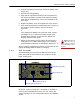
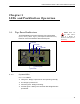
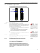
Table Of Contents

ES210 Hardware Guide: Installation
7
2 Unscrew the battery cover screws and lift the battery cover
(Figure 2.1).
3 Remove the existing battery.
4 Fully seat the replacement battery in the compartment in
the correct orientation: contacts at the bottom and facing
back (into the compartment), corner notch situated on the
lower right.
5 Replace the battery cover and retighten the cover screws.
6 If the replacement battery has previously been in service (in
the current or another ES210), skip the rest of this
procedure.
or
If the replacement battery has never been used, connect
the Bridge’s
DC Power input to the power adapter that
shipped with the Bridge, and connect the adapter to a
properly rated AC power outlet.
NOTE: The Battery
LED will not pro-
vide a charge indication
when the Bridge is pow-
ered off.
7 Permit the new battery to fully charge, as indicated by a
solid green
Battery LED, before using it for the first time.
(Complete LED indications are described in Section 3.1.1.)
Once the battery compartment is closed, you can power up and
operate the Bridge while the battery is charging.
2.1.3 Port Locations
The ES210 Bridge’s power inlet and Ethernet and antenna
ports, along with the LED indicators, are located on the top
panel, shown below.
Figure 2.2. ES210 Bridge Port Locations
By default, Fortress Security (a.k.a. encryption) is enabled on
the
WAN port and disabled on the Ethernet port. These and
other port settings are user configurable (see the GUI Software
Guide).
Wi-Fi antenna port (RP-TNC female)
GPS antenna port (SMA)
Ethernet port
(RJ-45)
WAN Ethernet port (RJ-45)
DC power input (with tethered cap)