
- Fortress Wireless Access Bridge User Guide


Fortress Bridge: Monitoring and Diagnostics
78
Stat2
can exhibit:
solid green - The Bridge is operating in root mode.
off - The Bridge is operating in non-root mode.
Clr
can exhibit:
fast green flash - The Bridge is passing cleartext
(unencrypted data) in the encrypted zone.
Fail
can exhibit:
off - The Fail LED does not apply to version 2.6.x of the
Fortress Bridge software. It is reserved for future support
for failover Bridge deployments.
Pwr
can exhibit:
solid green - The Bridge is powered on, either through the
+48V DC adapter inlet or the WAN port’s PoE connection.
off - Bridge is powered off.
5.6.2 Radio LEDs
The Bridge’s internal radios are each associated with a pair of
front-panel LEDs, labeled
Radio1 and Radio2.
Radio LEDs are arranged one above the other. Each radio then
has an associated upper and lower LED.
When the radio’s
LED RSSI Monitor is Disabled (the default) the
Radio1 and Radio2 LEDs behave as shown below. (The LED
RSSI Monitor and associated LED behaviors are described in
Section 3.3.2.7).
The upper LED can exhibit:
intermittent green flash - The radio is passing traffic.
The lower LED can exhibit:
solid green - The meaning depends upon the radio’s mode
settings:
In AP or Root Bridge modes - The radio is active and
acting as an AP or a root Bridge.
In Non-Root Bridge mode - The radio is connected to the
root Bridge.
off - This state is meaningful only for a radio in Non-Root
Bridge
mode and indicates that the radio is not connected
to the root Bridge.
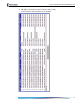
color/behavior upper LED lower LED both LEDs all four LEDs
solid green
n/a
in
AP or Root Bridge modes:
active
in
Non-Root Bridge mode:
connected to root
n/a n/a
intermittent green
passing traffic n/a n/a n/a
solid amber
n/a n/a n/a firmware error
off
n/a
in
Non-Root Bridge mode:
not connected to root
radio
disabled
both radios
disabled