
- Fortress Wireless Access Bridge User Guide

Fortress Wireless Access Bridge: Installation
12
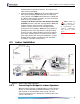
2.4.1 Connecting the Bridge for Preconfiguration
WARNING: To
comply with FCC
rules, antennas must be
professionally installed.
Improperly grounded
outdoor antennas pose a
particularly serious
safety hazard .
1 Position the Bridge so that it operates only within its safe
temperature range (14º–122º F/
–
10º–50º C).
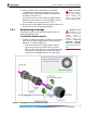
2 Connect a waterproof, standard 802.11a/b/g-capable
antenna with an N-type male connector to antenna port 1
(
ANT1).
3 Connect an antenna cable with an N-type male connector
between antenna port 2 (
ANT2) and a high-gain
omnidirectional or directional antenna. The antenna and
cable must be waterproof.
CAUTION: The
FCC requires co-
located radio antennas
to be at least 7.9" apart.
The Bridge’s antenna
connectors are only 5"
apart. Avoid directly
mounting two antennas to
the Bridge’s rear-panel
connectors.
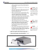
4 Connect the Bridge's WAN port to an external 802.3af PSE/
PoE (Power Sourcing Equipment/Power over Ethernet)
source, which—if the WAN port will connect to a satellite
link or a DSL or cable modem—provides an in-line
connection to the necessary network device.
(Outdoor Bridge installations require a PoE source; the 48V
power inlet cannot be connected when the Weatherizing Kit
is installed.)
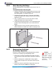
5 Connect one of the Bridge’s Auto-MDIX Ethernet LAN ports
(numbered
1–8) to a computer or switch on the wired LAN.
6 Verify that all link/activity and power LEDs illuminate for all
connected ports.
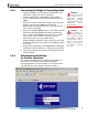
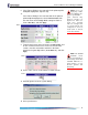
2.4.2 Preconfiguring the Bridge
for Outdoor Operation
The computer through which you configure the Bridge must
have a direct (non-routed) connection to the Bridge’s
unencrypted interface and an IP address in the same subnet
(192.168.254.0) as the Controller’s default IP address.