
SMA Sunny Island Integration Guide
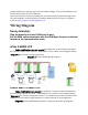
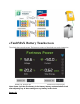
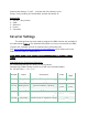
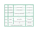
Table Of Contents
- Introduction, Contact info & Useful Links
- Introduction
- Unpack Batteries and Check Voltage
- 1. Unpack the batteries and turn each battery on by itself.
- 2. Note the voltage of each battery and serial number. The serial numbers are useful during warranty submittal.
- 3. The batteries must be within +/-0.5V of each other before commissioning. Groups of 4 batteries or more may require a narrower voltage range to commission properly.
- 4. Turn off the batteries and install them in parallel. Notes
- If the battery voltages are significantly different, one technique is to finish battery installation and only turn on the lowest voltage battery using the pushbutton. Charge the battery, and when the charging voltage is ~0.2V above the resting voltage...
- If the batteries are slightly more than +/-0.5V from each other, turning on the highest voltage batteries only will reduce their voltages, and turning on the lowest voltage batteries only will lower the highest voltage. Likewise, turning on the lowest...
- Use of the Fortress firmware update tool can help speed up commissioning times. Fortress installers should request a firmware update tool by filling out a support ticket at https://support.fortresspower.com
- Wiring Diagram
- Sunny Island(s):
- Plug the batteries into the COM Synch In port. Put the SMA canbus terminator into the COM Sync Out port on the last inverter in the communication chain. eFlex 5.4kWh LFP
- eVault Max 18.5kWh LFP
- eVaultMAX Battery Touchscreen
- Inverter Settings

222-06
CycTmEqu
Equalization timer
180 days
222-07
ChargVtgBoost
Cell nominal charge
2.26V
222-08
ChrgVtgFul
Cell full charge
2.3 V (55.2V)
222-09
ChrgVtgEqu
Cell equalization charge
2.3 V (55.2V)
222-10
ChrgVtgFlo
cell float charge
2.3 V (55.2V)
222-12
AutoEquChrgEn
auto equalization
2.2 V (52.8V)
226-01
BatChrgVtgMan
manual set battery charge
voltage with disabled BMS
54.5 V
226-02
BatDiChgVtg
min charge V of battery
48 V
226-03
BatDiChgVtgStr
start voltage after under voltage
51.2 V
231
External Settings
user defined settings
232-07
GdVldTm
minimum time for grid in range
<5 sec
232-08
GdMod
grid interface
user defined
232-09
GdRvPwr
permissible grid back feed
user defined
232-41 GdSocEna
activate grid request based on
soc
user defined or per
222 01-06
234/235
Generator Settings
user defined
240
Critical Load Panel Relay Settings
user defined