
SMA Sunny Island Integration Guide
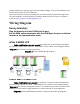
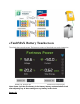
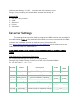
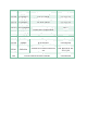
Table Of Contents
- Introduction, Contact info & Useful Links
- Introduction
- Unpack Batteries and Check Voltage
- 1. Unpack the batteries and turn each battery on by itself.
- 2. Note the voltage of each battery and serial number. The serial numbers are useful during warranty submittal.
- 3. The batteries must be within +/-0.5V of each other before commissioning. Groups of 4 batteries or more may require a narrower voltage range to commission properly.
- 4. Turn off the batteries and install them in parallel. Notes
- If the battery voltages are significantly different, one technique is to finish battery installation and only turn on the lowest voltage battery using the pushbutton. Charge the battery, and when the charging voltage is ~0.2V above the resting voltage...
- If the batteries are slightly more than +/-0.5V from each other, turning on the highest voltage batteries only will reduce their voltages, and turning on the lowest voltage batteries only will lower the highest voltage. Likewise, turning on the lowest...
- Use of the Fortress firmware update tool can help speed up commissioning times. Fortress installers should request a firmware update tool by filling out a support ticket at https://support.fortresspower.com
- Wiring Diagram
- Sunny Island(s):
- Plug the batteries into the COM Synch In port. Put the SMA canbus terminator into the COM Sync Out port on the last inverter in the communication chain. eFlex 5.4kWh LFP
- eVault Max 18.5kWh LFP
- eVaultMAX Battery Touchscreen
- Inverter Settings

voltage batteries as a group will raise the lowest voltage. Then, all the batteries can
be turned on within a 0.5/V difference.
Use of the Fortress firmware update tool can help speed up commissioning times.
Fortress installers should request a firmware update tool by filling out a support
ticket at https://support.fortresspower.com
Wiring Diagram
Sunny Island(s):
Plug the batteries into the COM Synch In port.
Put the SMA canbus terminator into the COM Sync Out port on the last
inverter in the communication chain.
eFlex 5.4kWh LFP
Cable modifications are not needed to establish a communication between
the Fortress Power eFlex 5.4 and SMA 6048-US units. Refer to the diagram below
(Diagram 1) for further wiring instructions.
Diagram 1: eFlex 5.4kWh Wiring Diagram
eVault Max 18.5kWh LFP
Cable modifications are needed to establish a communication between the
Fortress Power eVault 18.5 and SMA 6048-US units. Refer to the diagram below
(Diagram 2) for further wiring instructions. The modifications of the communication
cables are to be made using a keystone or other methods of pin assignment.
Diagram 2: eVault MAX Battery-Inverter Communication Wiring Diagram