
Schneider Electric Integration Guide
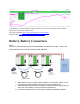
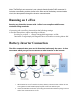
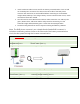
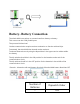
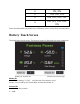
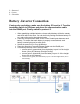
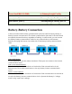
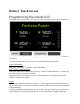
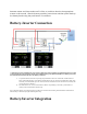
Table Of Contents
- Unpack Batteries + Check Voltage
- 1. Unpack the batteries and turn each battery on by itself.
- 2. Note the voltage of each battery and serial number. The serial numbers are useful during warranty submittal.
- 3. The batteries must be within +/-0.5V of each other before commissioning. Groups of 4 batteries or more may require a narrower voltage range to commission properly.
- 4. Turn off the batteries and install them in parallel. Notes
- If the battery voltages are significantly different, one technique is to finish battery installation and only turn on the lowest voltage battery using the pushbutton. Charge the battery, and when the charging voltage is ~0.2V above the resting voltage...
- If the batteries are slightly more than +/-0.5V from each other, turning on the highest voltage batteries only will reduce their voltages, and turning on the lowest voltage batteries only will lower the highest voltage. Likewise, turning on the lowest...
- Use of the Fortress firmware update tool can help speed up commissioning times. Fortress installers should request a firmware update tool by filling out a support ticket at https://support.fortresspower.com
- Schneider Monitoring w/Fortress
- Battery-Battery Connection
- Running on 1 eFlex
- Battery-Inverter Connection
- Battery- Battery Connection
- Battery Touch Screen
- Battery -Inverter Connection
- Battery-Battery Connection
- Battery Touch Screen
- Battery-Inverter Connection
- Battery/Inverter Integration
- Universal Parameter Settings (Closed Loop)
- Universal Parameters Settings (Open Loop)
- Important Note
- Off-Grid
- AC Coupling, Back Up
- Grid-Tied Export
- Self-Consumption (Zero Grid Export)
- Generator Settings
- Firmware Updates
- Voltage to % Chart

3 = Reserved
4 - Victron
5 = Schneider
Battery -Inverter Connection
If using only one battery, make sure the battery ID is set to 0. Turn the
terminator switch to 120ohms and place the communication cable
into the RS485 port. Finally switch to protocol 5.
1. When paralleling multiple batteries, choose which battery will be the master
and which will be the slave. You can do this by Setting the Master battery ID
to 1 and set the rest in chronological order.
2. Place the communication cable on the Comm Parallel ports between each
battery. To confirm that each battery is properly commissioned, each
battery’s status light must be solid green.
3. Switch the protocol ID to 5 on all batteries.
4. Place the remaining Format B Ethernet Cable onto the Rs485 port.
5. Cut and strip the end of the Format B cable
1. connect wire 3 (green/white) from the battery to port 9 of the Insight
Home (18 on the Gateway & Insight Facility)
2. connect wire 5 (blue/white) from the battery to port 11 of the Insight
Home (20 on the Gateway).
3. connect wire 6 (green) from the battery to port 7 of the Insight Home (16 on
the Gateway).