
Evault Max Install Manual

16
V4.2 11-02-21
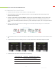
4
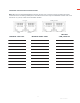
Victron CANBUS
5
Schneider MODBUS
6
Reserved
7
Reserved
8
Reserved
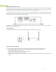
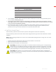
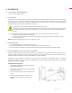
8. Use a CAT5/5e or greater cable to connect the CAN or RS-485 port of master battery (the Battery ID set
as 1) to inverter communication port.
9. Turn ON the inverter breaker, then turn ON all battery DC breakers, and then press the button of master
battery (Battery ID 1) for 8+ seconds to turn off. Finally, press the button on the master battery for 3+ seconds
to start the automatic PARALLEL PROCESS.
10. The master battery orders the lowest voltage battery of the whole system to pre-charge and turn on
relay, and request charge current from inverter. As the battery voltage increases, batteries join the
parallel circuit one by one. After all batteries are in parallel, the process ends.
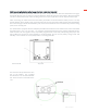
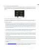
4.7 BATTERY CONNECTIONS
Wire the battery cables and connect them to positive and negative common bus respectively.
For parallel battery connections ensure identical wire lengths and wire type from each eVault Max to the DC
combiner.
NOTE: When installing multiple units ensure the recommended spacing distance among units of at least
5inches (12mm).
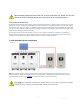
1. Connect the positive and negative cables from the DC combiner to the inverter.
2. Switch the battery breaker to the “ON” Position
3. Switch the inverter breaker to the “ON” Position
CAUTION! If paralleling the eVault Max 18.5 batteries without connecting them via RJ45 cable(s),
please make sure the difference between the highest voltage and lowest voltage does not exceed
0.5 volts. A large current flow from the higher voltage battery to the lower voltage battery and could
potentially damage one or both batteries. Resulting damage to the battery will void the warranty.
CAUTION! Verify polarity at all connections with a standard voltmeter before energizing the
system. Reverse polarity at the battery terminals will void the Warranty and destroy the batteries. Do
not short circuit the battery.