
Evault Max Install Manual

15
V4.2 11-02-21
Procedure to Parallel eVault Max Batteries
4.6 COMMUNICATION CONNECTIONS
1. Confirm that each battery DC circuit breaker is in the “OFF” position.
2. Wire each battery to your systems battery combiner. Connect the applicable AC and DC wiring on the
inverter side of the system.
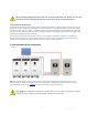
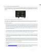
3. Connect the first eVault COM_Parallel OUT to the input of the next eVault’s IN port. Each unit comes with
one RJ45 cable for this purpose. If the cable is missing, please make sure the cable you purchase on the
market meets the following standards, CAT5/5e or greater, 24AWG pure copper, this is most typical ethernet
cables..
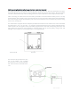
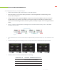
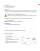
4. Per Fig 1. ensure the communication matching resistor of the first and last battery is set as 120Ω, while
the others are set to OFF.
5. Press the button on the front of each battery for approximately 8 seconds one by one, until all batteries start
up.
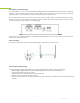
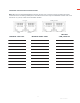
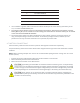
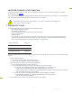
6. Touch the battery LCD to set “Battery ID” from 1 to N (Parallel number) as illustrated in the picture below.
7. Touch the LCD to set Inverter “Protocol ID” to the following:
PROTOCOL ID
SUPPORT INVERTER PROTOCOL
1
Fortress Power/Sol-Ark MODBUS
2
SMA CANBUS
3
Fortress Power CANBUS
Figure 1