
eVault Max 18.5kWh Lithium Ferro Phosphate (LFP) Installation

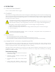

9. Turn ON the inverter breaker, then turn ON all battery DC breakers, and then press the button of master
battery (Battery ID 1) for 6+ seconds to turn o. Finally, press the button on the master battery for 3+ seconds
to start the automatic PARALLEL PROCESS:
The master battery orders the lowest voltage battery of the whole system to pre-charge and turn on relay,
and request charge current from inverter. As the battery voltage increases, batteries join parallel circuit one
by one. After all normal batteries complete the parallel, the PARALLEL PROCESS ends.
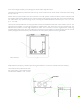
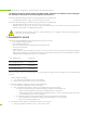
4.6 PARALLEL CONNECTION
Wire the battery cables and connect them to positive and negative common bus respectively as
described in the page 9.
CAUTION! For parallel connecting: Maintain identical wire lengths and wire construction from each
Fortress Power Battery terminal to the common bus.
CAUTION! For connecting multiple units: Maintain the recommended distance among units - at least
5inches (12mm).
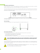
1. Connect the positive and negative common bus to the inverter.
2. Please put battery breaker into “ON” Position
3. Please put inverter breaker into “ON” Position
CAUTION! If Paralleling the eVault Max 18.5 batteries without connecting them via RJ45 cable(s),
please make sure the dierence between the highest voltage and lowest voltage does not exceed 0.5
volts. A large current ow from the higher voltage battery to the lower voltage battery could potentially
damage one or both batteries. Resulting damage to the battery will void the warranty.
CAUTION! Verify polarity at all connections with a standard voltmeter before energizing the system.
Reverse polarity at the battery terminals will void the Warranty and destroy
the batteries. Do not short circuit the batteries.
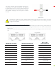
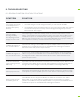
4.7 LCD SCREEN AND ALARM WARNING
The LCD display on the front of eVault Max provides Battery Voltage (V), Charging and Discharging Current (A),
State of Charge (SOC), as well as Charging and Discharging Power Output (KW). Please note, when the battery is
charging, the Current (A) will show negative value; while during the discharging the Current (A) is positive.
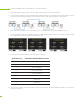
The green light (RUN) indicates system is running properly.
The red alarm light (ALARM) will turn on, if the battery experiences
one of those scenarios: High voltage (HV); Low voltage (LV); HT (High
Temperature): LT (Low Temperature); Open Circuit (OC) and Short
Circuit (SC).