
Pseries Installation Guide

P-Series Installation and Operation Guide, version 2.3.1.2 9
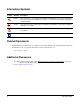
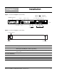
Figure 1 P-Series P10 Appliance (Front View)
IDENTIFY
LAN 2
LAN 1
VGA
SERIAL
USB x2KEYBOARD
MOUSE
POWER
RJ-45 SERIAL
E0 & E1 IP ADDRESS
MANAGEMENT
PORTS
LEDs
POWER
DISPLAY
(E0)(E1)
MIRROR
PORT 1
(P1)
PORT 0
(P0)
PORT 0 (M0)
MIRROR
PORT 1 (M1)
HARD
DISK
fn9000007
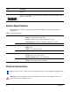
Figure 2 P-Series P10 Appliance (Rear View)
AC POWER RECEPTACLE
MAIN POWER
fn9000009
01234567
SERIAL NUMBER
Chapter 1 Installation
Label Description
(LCD screen) The LCD screen displays the IP address of the appliance next to either “e0:” or “e1:”,
which represent LAN ports 1 and 2, respectively.
Port 1, Port 0 These two ports are sensing ports through which traffic is forwarded. They accept 10G
XFP modules.
(unlabeled RJ-45 serial
port next to IDENTIFY)
This port is not used.
IDENTIFY This LED is not used.
HDD This LED is blue when the hard disk is accessed.
PWR This LED is green when the power is on.