P-Series Installation and Operation Guide Version 2.3.1.
Copyright 2008 Force10 Networks® All rights reserved. Printed in the USA. January 2008. Force10 Networks® reserves the right to change, modify, revise this publication without notice. Trademarks Force10 Networks® and E-Series® are registered trademarks of Force10 Networks, Inc. Force10, the Force10 logo, and P-Series are trademarks of Force10 Networks, Inc. All other brand and product names are registered trademarks or trademarks of their respective holders.
Contents Contents . . . . . . . . . . . . . . . . . . . . . . . . . . . . . . . . . . . . . . . . . . . . . . . . . . . . . . . . . . . . . . . . . . . 3 Preface About this Guide . . . . . . . . . . . . . . . . . . . . . . . . . . . . . . . . . . . . . . . . . . . . . . . . . . . . . . . . . . . . 7 Objectives . . . . . . . . . . . . . . . . . . . . . . . . . . . . . . . . . . . . . . . . . . . . . . . . . . . . . . . . . . . . . . . . . . . . . . 7 Audience . . . . . . . . . . . . . . . . . . . . . . . . .
Mirroring to Another Device . . . . . . . . . . . . . . . . . . . . . . . . . . . . . . . . . . . . . . . . . . . . . . . . . . . . 24 Chapter 4 Graphical User Interface . . . . . . . . . . . . . . . . . . . . . . . . . . . . . . . . . . . . . . . . . . . . . . . . . . . . . 25 GUI Commands . . . . . . . . . . . . . . . . . . . . . . . . . . . . . . . . . . . . . . . . . . . . . . . . . . . . . . . . . . . . . . . . . 26 Managing Rules, Policies, and Firmware . . . . . . . . . . . . . . . . . . . . . . . .
Chapter 8 Compiling Rules. . . . . . . . . . . . . . . . . . . . . . . . . . . . . . . . . . . . . . . . . . . . . . . . . . . . . . . . . . . . 55 Creating Rules Files . . . . . . . . . . . . . . . . . . . . . . . . . . . . . . . . . . . . . . . . . . . . . . . . . . . . . . . . . . . . . 55 Rules Capacity . . . . . . . . . . . . . . . . . . . . . . . . . . . . . . . . . . . . . . . . . . . . . . . . . . . . . . . . . . . . . . . . . 55 Compiling Rules . . . . . . . . . . . . . . . . . . . . . . . . . . .
Unix Commands . . . . . . . . . . . . . . . . . . . . . . . . . . . . . . . . . . . . . . . . . . . . . . . . . . . . . . . . . . . . . . . 125 vi Commands . . . . . . . . . . . . . . . . . . . . . . . . . . . . . . . . . . . . . . . . . . . . . . . . . . . . . . . . . . . . . . . . . . 126 Appendix E Glossary . . . . . . . . . . . . . . . . . . . . . . . . . . . . . . . . . . . . . . . . . . . . . . . . . . . . . . . . . . . . . . . . . 127 Appendix F Technical Support . . . . . . . . . . . . . . . . . .
Preface About this Guide Objectives This document provides installation and operation instructions for the P-Series P10 appliance. Audience This guide is intended to be used by network engineers. The P10 is a Unix-based product that runs rule management software based on Linux and FreeBSD. As such, understanding how to operate the appliance requires a basic knowledge of Unix, including the vi editor.
Information Symbols Symbol Warning Description Danger This symbol warns you that improper handling and installation could result in bodily injury. Before you work on this equipment, be aware of electrical hazards, and take appropriate safety precautions. Caution This symbol informs you that improper handling and installation could result in equipment damage or loss of data. Warning This symbol informs you that improper handling could reduce your component or system performance.
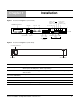
Chapter 1 Installation Figure 1 P-Series P10 Appliance (Front View) PORT 1 (P1) MOUSE SERIAL PORT 0 (P0) MIRROR PORT 0 (M0) RJ-45 SERIAL VGA fn9000007 E0 & E1 IP ADDRESS D I S P L AY MIRROR PORT 1 (M1) POWER KEYBOARD USB x2 LAN 2 (E1) LAN 1 (E0) IDENTIFY HARD POWER DISK LEDs MANAGEMENT PORTS Figure 2 P-Series P10 Appliance (Rear View) 01234567 MAIN POWER fn9000009 AC POWER RECEPTACLE SERIAL NUMBER Label Description (LCD screen) The LCD screen displays the IP address of the applian
Label Description (Power Button) This button turns the appliance on and off. Press and hold the button to turn off the appliance. (Laser Warning) This label in the bottom right corner of the appliance indicates that the appliance is a Class 1 laser product that emits invisible laser radiation. This product complies with CDRH, 21 CFR 1040. FN00048A System Specifications The specifications in Table 1 apply to the P-Series P10 appliance, Force10 catalog number PB-10GE-2P.
Step Task 1 Review the system specifications and ensure that your operating and storage conditions meet the stated requirements. 2 Connect the power cable, a keyboard, and a monitor to the appliance. 3 Connect the LAN 1 port on the appliance to the local area network where DHCP is available. If a DHCP server is not available, an IP address can be assigned manually; see “Configuration” on page 12. 4 Install XFPs in the ports that will be used.
Booting During booting you can select the OS of your choice. The management ports are configured for DHCP and probe for an IP address, gateway, and name server. The IP address is displayed on the LCD screen. When the appliance is powered up, all packets are forwarded between its ports by default until the firmware and device drivers are loaded.
Warning: Stop all traffic from flowing through the appliance, and disconnect all cables from the XFPs before proceeding. Step Task Command 1 Save earlier configuration files and firmware by copying the directory /usr/local/pnic to the home directory. cp -Rf /usr/local/pnic/ /home 2 Create a new sub-directory in the home directory for the upgrade package. mkdir ~/upgrade_directory 3 From the root directory, secure copy the file filename from a server to the upgrade directory you created.
Step 13 14 Task Command Re-compile all rules firmware with the new compiler located in the directory pnic-compiler. cd upgrade_directory/pnic-compiler Install pre-compiled firmware if needed.
Chapter 2 Getting Started To begin inspecting and filtering traffic you must: 1. Select firmware and dynamic rules 2. Set capture/forward policies 3. Check for proper operation by generating traffic across the appliance. Step Task 1 As root, enter the command pnic gui from the Unix command line to invoke a graphical user interface (GUI). 2 Enter the command m from the GUI command line. 3 Select Manage Firmware from the Rule Management GUI, then select “null” firmware and confirm.
Getting Started
Chapter 3 Introduction The P-Series P10 Intrusion Detection and Prevention System (IDS/IPS) appliance employs Dynamic Parallel Inspection (DPI) technology. It uses a Multiple Instruction Single Data (MISD) massively parallel processor that executes thousands of security policies or traffic capture operations on the same data stream at the same time. DPI synthesizes individual security policies and packet analysis algorithms and maps them directly into silicon hardware "gates.
Figure 3 illustrates how all matched packets are copied and transmitted by mirror ports. Note: Mirroring is automatically enabled when the mirroring port is connected to another network device. Mirroring is not controlled through the CLI.
Firmware is a set of rules that has been transformed—using a compiler—from Snort syntax into a form suitable for uploading to the FPGA. Two sets of sample rules files have been compiled into firmware and are available to be uploaded to the FPGA using either of two firmware management methods (see “Rule Management” on page 19). Table 2 describes each sample rules file. Table 2 Sample Rules Files Rule Set Description evasion.
Inline Deployment Use the P-Series for inline traffic inspection in IPS or firewall applications at 10-Gigabit line rate (Figure 4). • • For IPS deployment, no special configuration is needed; the P-Series is in inline IPS mode by default. For a firewall deployment, enable drop mode (see Command Line Reference on page 79).
Highly-available Deployment Use optical bypass switches with the P-Series for a highly-available, redundant deployment, as shown in Figure 6. Both the appliances have the same configuration so that in the event of a power failure on one device, the other continues to operate, and the detection engine remains intact. In the event that both devices experience a power failure, the traffic continues to flow through the bypass switches.
Figure 8 Passive Deployment with Aggregation using a Network Tap Network Tap 10-Gigabit 10-Gigabit P0 P-Series P10 fn90033mp Figure 9 Passive Deployment with Aggregation using a SPAN port Network Switch with SPAN port Port to Monitor SPAN Port P0 10-Gigabit P-Series P10 fn90034mp Capturing Matched Traffic P-Series supports capturing matched traffic for analysis.
Capturing to a Host CPU Captured traffic can be sent to a host CPU through a libpcap library interface, where it can be made available to applications for analysis. A typical implementation provides IDS/Snort acceleration because of the hardware assist.
Mirroring to Another Device Mirror captured traffic out of the 1-Gigabit mirroring ports to use the P-Series as an IDS accelerator or as part of an integrated security monitoring solution.
Chapter 4 Graphical User Interface The GUI can be used to: • • • • • Start and stop the DPI Load firmware Compile and load dynamic rules Manage the runtime parameters Manage the capture/forward policies for rules Note: Using the GUI requires the super user privilege. To invoke the GUI: Step 1 Task Invoke the GUI by entering the command pnic gui. Note: The OS environment variables are set such that the pnic gui command can be executed from any path.
GUI Commands From the Runtime Statistics display, you can enter commands to control the DPI (see Table 3, or enter the h command from the GUI command line). Figure 13 Runtime Statistics - FPGA Unloaded CPU(s): FlowTimeout=16 Packets/flow=0 Truncation=0 Irq period=5ms fn9000010 N/A/1 0.0% user, 0.0% nice, 0.0% system, 0.0% interrupt, 100% idle Note: GUI commands that require a subsequent value entry have the current value displayed in parentheses at the prompt.
Table 3 GUI Commands Command Description u Brings the OS network interface up and enables matching. This is similar to the command s, but it does not load/reload the driver. It is only valid after the command s has been executed. x Toggles the direct memory access (DMA) off and on to enable or disable capturing to the host, respectively. z Disables the DMA and brings the interface down, in succession. This is equivalent to issuing the commands pnic down and pnic off, in succession.
Table 4 Managing Rules Using the GUI Option Description Edit Rules This option invokes the vi editor on the file rules.custom in the /user/local/pnic/0 directory (see “Editing Dynamic Rules with the GUI” on page 28). • • Manage Rules You can add, delete, or modify dynamic rules for either of the processing channels (see Appendix D , on page 125 for information on vi). The rules are automatically compiled and loaded into the appliance; you are prompted to confirm these actions.
To modify dynamic rules: Step Task 1 Enter the m command from the GUI command line (see “GUI Commands” on page 26) to access the main rule management GUI (see Figure 14). 2 Select Edit Rules to invoke the vi editor (see Figure 15). 3 Add, delete, alter, or uncomment rules using vi commands (see Appendix D , on page 125). 4 You are prompted to confirm your changes upon exiting the editor.
fn9000013 Figure 16 Managing Capture/Forward Policies GUI fn9000014 Figure 17 Capture/Forward Policies GUI Selecting Firmware with the GUI Firmware is a set of rules that has been transformed—using a compiler—from Snort syntax into a form suitable for uploading to the FPGA.
To select firmware: Step Task 1 Enter the m command from the GUI command line (see “GUI Commands” on page 26) to access the main rule management GUI. 2 Select Manage Firmware (see Figure 18). 3 Use the arrow keys to highlight the desired firmware and the Select option, and press the Enter key. See “Firmware Filename Description” on page 62 for information on identifying firmware by their filenames. 4 Confirm your selection, and exit the GUI.
The remaining lines report the cumulative number of events and the rate of those events. A description of each line is given in Table 6. Figure 19 Runtime Statistics for Channel 0 and 1—FPGA Loaded CPU(s): 0.0% user, 0.0% system, 0.0% nice, 100.0% idle Dev: 8002 - Type: PNIC-0 - FirmwareID: 64 - Ver:2.
Table 6 Runtime Statistics Description Statistic Description Total Packets Shows the number of packets received by the ports. This is a Layer 1 statistic and is independent of whether the OS interface is up or down. TCP/UDP/ICMP/Other Reports the type of packets received during matching. Other includes all non-IP types and all IP types other than TCP, UDP, and ICMP. Capture Packets Counts the total number of packets matched and captured by some policy.
Graphical User Interface
Chapter 5 Web-based Management You can manage and monitor the P-Series on the web using the Force10 Networks P-Series Node Manager. Note: The web-based GUI is supported on Linux only, which is the default OS, and requires software version 2.3.0.0 or newer. Launching the P-Series Node Manager Note: The Web-based GUI is best viewed with a minimum screen resolution of 1280x800. You must also have Java Run Time Environment (JRE) installed with the “Use JRE X.Y.
Note: Stop the secure HTTP service using the command pnic web-gui-stop (see Appendix A , on page 79).
Web-browser Security Certificates The P-Series Node Manager client and the server communicate via HTTPs. All transactions are encrypted, and thus protected, by the SSL protocol. The SSL certificate is a self-signed certificate that is not signed by a trusted Certificate Authority (CA). While trying to launch the P-Series Node Manager, your web browser might display an alert indicating that the security certificate was not issued by trusted CA or a similar warning (Figure 22).
Monitoring System Performance Monitor system performance from the Home panel (Figure 23). The Home panel is displayed after logging into Node Manager. It displays basic system information, card, interface, and resource information, as well as CPU and memory usage over time.
Managing Firmware Images Manage the software image from the Image Management panel (Figure 24). The Image Management panel provides options for compiling and deleting an image. It displays a list of available images along with the currently applied image and its details. Figure 24 P-Series Node Manager: Image Managment Panel Managing the Network Interface Card Manage the network interface card from the Card Management panel.
Figure 25 P-Series Node Manager: Card Management Panel 40 Web-based Management
Managing Policies Manage policies from the Policy Management panel (Figure 26). The Policy Management panel provides you with a list of available static and dynamic rules available for the currently running image. It also has the provision for adding, modifying, and deleting dynamic rules. P-Series Installation and Operation Guide, version 2.3.1.
Figure 26 P-Series Node Manager: Policy Managment Panel 42 Web-based Management
Chapter 6 Network Security Monitoring A key aspect of network security deployment is the ability to monitor the network for security events, analyze them, and perform counter measures.
Installing the Sguil System To employ Sguil you must: 1. Install the sensor. See page 44. 2. Install the server. See page 44. 3. Install the client. See page 45. Note: You can download the server and client Sguil components directly from the Sguil website at http:// sguil.sourceforge.net/index.html. The solution uses a number of components which must be installed.
Step Task Command 4 Source the server configuration file. The default parameters in this file may be changed. source Configure-Inputs.sh 5 Compile and build the Sguil server package. Use the logging option to collect debugging information during compilation and redirect standard output and errors to a log file. gmake [> build.log 2>&1] 6 Install the Sguil server package. gmake install 7 (OPTIONAL) Set the debug flag to 1 in sguild.conf before executing Startserver.
Step Task 3 Configure the following parameters in the file sguil.conf: • Enable (1) or disable (0) the debug option • Set the browser path. • Set the Wireshark application path. • Set the TLS library path, as shown in Figure 28. • Set priority levels of the alert window. Figure 28 Setting the TLS Library Path # PATH to tls lib if needed (tcl can usually find this by default) #set TLS_PATH /usr/lib/tls1.4/libtls1.4.so # win32 example set TLS_PATH "c:/progra~1/Tcl/lib/tls1.4.1/tls14.
Running the Sguil System Running the Sguil Sensor Start the Sguil sensor using the command pnic sguil-sensor-start. Specify the IP address of the Sguil server, and confirm the action, as shown in Figure 29. Figure 29 Starting the Sguil Sensor root@# pnic sguil-sensor-start Enter the IP address of the Sguil-Server:192.16.130.246 *********************************************** INTERFACE NAME : pnic0 SGUIL-SERVER IP-ADDRESS : 192.16.130.
• • • • The rule file you are using should be mentioned in snort.conf file. A sample rule file under rules directory is already added and commented in snort.conf. Log files are stored in the installation sub-directory .../nsm/sguil/logs. When adding new rules to the file sample.rules, uncomment the line, “include sample.rules”in the file snort.conf. Snort rule syntax is different from P-Series rule syntax.
Running the Sguil Client To run the Sguil Client: Step Task 1 Open sguil.tk using the Wish application. A window appears, as shown in Figure 31. 2 Specify the IP address of the Sguil server, and your username and password. 3 Select the sensors to monitor (click “Select All” to monitor all sensors), and click “Start SGUIL” (Figure 32). Figure 31 Running the Sguil Client P-Series Installation and Operation Guide, version 2.3.1.
Figure 32 Selecting the Sensor to Monitor fn90027mp When the Sguil client starts and the client is properly connected to the Sguil server, the window in Figure 33 appears.
Chapter 7 Command Line Interface The command line interface (CLI) is an alternative to the GUI for managing the appliance. A script called pnic is used to perform the same management functions as the GUI. Invoke the pnic script using the command syntax pnic command; the OS environment variables are set such that this command can be executed from any path. CLI Commands CLI commands are given in Command Line Reference on page 79.
This feature can be enabled per channel. When MAC rewrite is enabled, the P10 appliance classifies the incoming traffic into one of 256 hash buckets to determine the value to be written to the LSB of destination MAC address. A hash function based on the source and destination IP addresses is used to calculate an 8-bit index for each incoming packet. The index is used to look up the LSB values to be written into the packet.
Removing VLAN Tags The P-Series can strip the VLAN tag from incoming packets before they exit the egress port. Enable the feature using the command pnic vlan-remove-enable. The frame CRC is recalculated when this feature is enabled. If an incoming packet is untagged, it is not changed. View the enable state of this feature using the command pnic showconf. P-Series Installation and Operation Guide, version 2.3.1.
Command Line Interface
Chapter 8 Compiling Rules The P-Series Network Interface Card Compiler (pnic-Compiler) produces user-defined firmware for the appliances. The user-defined input is a set of signature-based rules in Snort syntax, and compilation directives. The output of the compiler is a Xilinx bit file and ASCII mapping files that map specified signatures to internal configuration registers. The configuration registers are used to disable/enable rules or block packets.
Table 8 Compiler Configuration Options Compilation Option 1 Target Device Description Choose the model of your appliance. • The P10 requires type PB-10G-2P (see Figure 35 on page 58) 2 Match non-IP Traffic Answering Yes to this option matches packets that are not IPv4. This option should be set to No if only IP traffic is allowed.
Table 8 Compiler Configuration Options Compilation Option 7 Segmentation Evasion Rules Description The pnic-Compiler prepends a set of fixed rules—called evasion.rules — located in the pnic-compiler/rules directory. The rules help detect attacks which are using strategic TCP segmentation to avoid detection. It is best to include this file if Snort is being used as the front end.
Figure 35 pnic-Compiler Option 1-6 root@# gmake Makefile:2: mtp_configuration: No such file or directory bin/getparams2.
Figure 36 pnic-Compiler Option 6-7 Channel 1 Dynamic rules Please choose how many dynamic rules (5-20 recommended) Dynamic rules are rules that can be added without recompiling the firmware.
Figure 37 pnic-Compiler Option 8-9 Please choose the maximum number of bytes per signature (1024 recommended). Selecting a small number allows larger sets of signatures at the expense of more false positives. 1) 16 2) 32 3) 64 4) 96 5) 128 6) 256 7) 512 8) 1024 #? 8 Enter the firmware base-image name (press the Enter key to retain the default name: "snort_dos.rules.xc4vlx200-ff1513.10.10.32"): snort_dos.
Configuration and Generated Files Table 9 describes the files that are used or generated by the pnic-Compiler. Table 9 Configuration and Generated Files File Description pnic_*.bit Generated after compiling static rules. They /usr/local/pnic/0 are then renamed and copied to /usr/local/ pnic/firmware. When selecting firmware, the .bit files are symbolically linked to the corresponding renamed files in the firmware directory. pnic_*.mapping Generated after compiling static rules.
Firmware Filenames The pnic-Compiler creates new firmware — in the /usr/local/pnic/firmware directory — consisting of four .bit files and eight .mapping files. The default firmware filenames follow a naming convention designed to identify three properties: • • • The appliance that can use it The number of dynamic rules The maximum allowed number of half-bytes per rule Firmware files have the format: ....{0|1}.
Chapter 9 Writing Rules P-Series rule syntax is based on Snort. Both rule structures are described in this chapter. • • Snort Rule Syntax on page 63 P-Series Rule Syntax on page 66 Snort Rule Syntax Snort rules are descriptions of traffic plus a prescribed action that is taken if a packet matches that description. Rules are divided into two sections: • • Header: The header contains the action, protocol, source and destination IP addresses (with subnet masks), and the source and destination ports.
• • • pass directs Snort to ignore the packet. activate directs Snort to generate an alert and activate another specified rule. dynamic directs Snort to disregard the rule until it is activated by another rule. Once activated, the action defaults to log. Note: The default actions for the P-Series are different from Snort. See “P-Series Rule Syntax” on page 66. The meaning of the Snort action keyword dynamic is not the same as P-Series dynamic rules.
Ports Port numbers may be specified by the keyword any, a single port number, ranges, and by negation. any specifies any port. Static ports are indicated by a single port number, for example, 23 for Telnet. Port ranges can be specified using a colon as a range operator. It can be applied in three ways, as shown by Table 15. Table 15 Rules Containing the Port Number Range Operator log udp any any -> 192.168.1.0/24 1:1024 log udp log tcp any any -> 192.168.1.0/24 :6000 log tcp any :1024 -> 192.168.1.
Destination Address and Port The destination address and port follow the direction operator. The syntax of these parameters are the same as the source address and port. See “Source Addresses” on page 64, and “Ports” on page 65. Snort Rule Options Options are made of a keyword and an argument. An argument is the packet data against which the rule is matched. Option keywords are followed by a colon, and each option is puncutated with a semi-colon.
Table 19 Supported Snort Keywords for Static and Dynamic Rules Keyword Static Dynamic depth No No dsize Yes No flags Yes Yes, no wild card flow Yes No fragbits Yes No fragoffset Yes No icmp_id Yes Yes icmp_seq Yes Yes icode Yes Yes id Yes Yes ip_proto Yes Yes itype Yes Yes offset No No nocase Yes No protocol ICMP, UDP, TCP, IP ARP, ICMP, UDP, TCP, IP seq Yes Yes source address Yes Only /8/16/24/32 masks destination address Yes Only /8/16/24/32 masks s
Writing Stateful Rules Stateful matching improves the accuracy of detection because it adds ordering when specifying behaviors across multiple matching events. State transitions in the P-Series follow a non-cyclic pattern; no state transitions may erase any of the previous states. New state transitions are simply recorded via a non-destructive, additive operation. As new states are produced, they are bitwise “OR-ed” with the current states contained in the per-flow register Cf., which is 16 bits wide.
Pre-match Condition — the S Value The value in register Cf is presented to all the signatures simultaneously during matching. Cf must have all the bits specified by si (in addition to matching mi) in order for the signature i to trigger. In other words, if the result of the logical “AND” of register Cf with si is non-zero and equal to si, the signature is allowed to trigger. Otherwise the signature is not triggered. Therefore value si is referred to as the pre-match bit pattern.
When a packet is stored in either Temporary Memory or Match Memory, a pointer to the previously stored packet in the same flow (contained in a portion of the flow register Cf) is also stored. Thus a packet stored in Match Memory may reference another packet stored in Temporary Memory, which in turn may reference more packets, thus forming a linked list of partial matches, starting with a packet stored in Match Memory.
You can inspect Signatures 4, 5, and 6, and verify that they trigger a match and place a packet in Match Memory — thus alerting the host — if three consecutive packets are seen with size between 0 and 100. The third packet references the previous two stored in Temporary Memory. Thus, once the third packet is received, the three segments are presented to the host through the DPI network interface.
The start of the state machine is prompted by a SYN; state 1 is reached if a packet of length greater than 0 but less than 20 is detected; state 2 is reached if a packet of length 1 is received right after a SYN or a second packet of length greater than 0 but less than 20 is detected; the final state is reached if a packet of a length between 0 and 100 is seen. This state diagram was derived from observing common fragmentation evasion patterns; it seems to catch most of them.
Anomalous TCP Flags Some TCP packets with anomalous flags are captured by default to provide scan detection software diagnosis information. Table 24 shows rules which were derived from the Snort scan pre-processor.
Writing Rules
Chapter 10 Firewall Deploying the P-Series as a Firewall By default the P-Series is an IDS/IPS system; the P-Series forwards all traffic by default and blocks packets only if it matches a rule. You can deploy the P-Series as a limited firewall by enabling Drop mode. In Drop mode, the P-Series blocks all traffic by default and forwards traffic only if it matches a rule. P-Series Installation and Operation Guide, version 2.3.1.
Enabling the Firewall Enable Drop mode using the command pnic default-drop-enable. Disable Drop mode using the command pnic default-drop-disable. These commands are shown in Figure 39. Figure 39 Enabling and Disabling Drop Mode [root@localhost ~]# pnic default-drop-disable No device number specified. Assuming device 0 Drop mode Disabled *** Disabling Default-Packet-Drop on card:0 successful! *** Temporary memory enabled. [root@localhost ~]# pnic default-drop-enable No device number specified.
Allowing Traffic through the Firewall To allow packets through the firewall you must write rules so that packets that you want the appliance to forward match those rules. Rules can be as simple as allowing traffic destined to a port. Stateful rules can be used to allow all traffic for an established connection. To allow non-IP traffic to pass through the firewall, you must select “Yes” for compiler option 2, as described in Table 8 on page 56.
Table 25 Sample Firewall Rules #permit: let through and do not log to the host #alert: let through and log to the host #deny: DO NOT let through and do not log to the host #divert: DO NOT let through and log to the host # S:; C: R: # A packet is matched if precondition matches the current state of that flow; # in that case the postcondition is ORed and applied to rewrite the state of that flow; # A precondition of 1 starts a new flow # logging should be set to 2 for mos
Appendix A Command Line Reference The command line interface (CLI) is an alternative to the GUI for managing the appliance. A script called pnic is used to perform the same management functions as the GUI. Invoke the pnic script using the commands in this chapter; the OS environment variables are set such that these command can be executed from any path.
• • • • • • • • • • • • pnic showconf on page 108 pnic show-firmwares on page 108 pnic showtech on page 109 pnic start on page 110 pnic stop on page 111 pnic temp-mem-disable on page 112 pnic temp-mem-enable on page 112 pnic updatemacvalue on page 113 pnic vlan-remove-disable on page 114 pnic vlan-remove-enable on page 114 pnic web-gui-start on page 115 pnic web-gui-stop on page 116 Note: The P10 does not support multiple network interface cards.
Related Commands pnic aggregate-mode-enable Receive both client-to-server and server-to-client traffic on one port. pnic aggregate-mode-enable Receive both client-to-server and server-to-client traffic on one port. This is the default behavior. Syntax pnic aggregate-mode-enable [number] Disable aggregate mode using the command pnic aggregate-mode-disable. Parameters Command History Example number Version 2.3.0.0 (OPTIONAL) Enter the number of the network interface card.
Parameters Command History Example number Version 2.3.0.0 (OPTIONAL) Enter the number of the network interface card. Range: 0-5 Default: 0 Introduced Figure 42 pnic apply-firmware Command Example 1 [root@localhost SW]# pnic apply-firmware No card number specified. Assuming card 0 Do you really want to apply a new firmware for card0 (y/n)? y Please enter the path or name of the firmware to apply: /usr/local/ pnic/firmware/null.xc4vlx200-ff1513.50.50.
pnic capture-off Disable the capturing of packets via direct memory access (DMA). Syntax Parameters Command History Example pnic capture-off number Version 2.3.0.0 Enter the number of the network interface card. Range: 0-5 Default: 0 Introduced Figure 44 pnic capture-off Command Example [root@localhost root@# pnic macrewrite-on SW]# pnic capture-off 0 No card number specified. Assuming card 0 No channel number specified. Assuming channel 0 *** Enabling Capture OFF set MACsuccessful.
Example Figure 45 pnic capture-on Command Example [root@localhost root@# pnic macrewrite-on SW]# pnic capture-on 0 No card number specified. Assuming card 0 No channel number specified. Assuming channel 0 *** Enabling Capture ON set MAC successful. rewrite on card:0 channel:0 is successful! [root@localhost SW]# Related Commands pnic capture-off Disable the capturing of packets via direct memory access (DMA).
pnic compilerules Transform the dynamic Snort rules contained in /usr/local/pnic/0/rules.custom into binary code suitable for the DPI processor. Syntax Parameters Command History Example pnic compilerules [number] number Version 2.0.0.1 (OPTIONAL) Enter the number of the network interface card. Range: 0-5 Default: 0 Introduced Figure 47 pnic compilerules Command Example [root@localhost SW]# pnic compilerules No card number specified.
Example Figure 48 pnic default-drop-disable Command Example [root@localhost SW]# pnic default-drop-disable No card number specified. Assuming card 0 *** Disabling Default-Packet-Drop on card:0 successful! *** Temporary memory enabled. *** Flow teardown disabled. [root@localhost SW]# pnic default-drop-enable Enable firewall functionality. pnic default-drop-enable [number] Disable firewall functionality using the command pnic default-drop-disable. Parameters Command History Example number Version 2.2.0.
Parameters Command History Example number Enter the number of the network interface card. Range: 0-5 Default: 0 -v Display a detailed output. Version 2.3.1.2 Added option -v. Version 2.0.0.1 Introduced Figure 50 pnic diag Command Example 1 [root@localhost pnic]# pnic diag No card number specified. Assuming card 0 Running PNIC diagnostic test needs to stop traffic matching. Do you want to proceed [n/y]? y *** Matching disabled. Test starting ... Waiting for matching to stop ...
pnic flow-teardown-disable Configure the appliance to reset the state of the flow only upon a timeout. This is the default behavior. Syntax Command History Example pnic flow-teardown-disable Version 2.3.1.2 Introduced Figure 52 pnic flow-teardown-disable Command Example [root@localhost SW]# pnic flow-teardown-disable No card number specified. Assuming card 0 *** Disabling Flow-Teardown on card:0 successful.
Example Figure 53 pnic flow-teardown-enable Command Example [root@localhost SW]# pnic flow-teardown-enable No card number specified. Assuming card 0 *** Enabling Flow-Teardown on card:0 successful. [root@localhost SW]# Usage Information Related Commands The flow teardown feature is coupled with the firewall feature. When default drop mode is enabled (command pnic default-drop-enable), the flow teardown is enabled by default.
Related Commands pnic macrewrite-on Enable MAC rewriting. pnic macrewrite-off Disable MAC rewriting. pnic updatemacvalue Update the LSB value for a particular hash index value. pnic gui Launch the graphical user interface. Syntax Command History 90 pnic gui Version 2.0.0.
Example Figure 55 pnic gui Command Example [root@localhost SW]# pnic gui CPU(s): 0.0% user, 0.0% system, 0.0% nice, 100.0% idle Dev: 8002 - Type: PNIC-0 - FirmwareID: 64 - Ver:2.
pnic help Display a list of all available commands, their syntax, and descriptions. Syntax Command History Example pnic help Version 2.3.0.0 Introduced Figure 56 pnic help Command Example [root@localhost SW]# pnic help No card number specified. Assuming card 0 Usage: pnic function_command pnic pnic pnic pnic pnic pnic pnic pnic pnic pnic pnic pnic pnic pnic pnic pnic pnic pnic pnic aggregate-mode-disable <0|...|5> apply-firmwares <0|...|5> <-f> capture-on <0|...
pnic linkdown Disable the physical link. Syntax pnic linkdown [number] [channel] Enable a physical link using the command pnic linkup. Parameters Command History Example number Enter the number of the network interface card. Range: 0-5 Default: 0 channel Enter the channel number Range: 0-1 Default: 0 Version 2.0.0.1 Introduced Figure 57 pnic linkdown Command Example [root@localhost SW]# pnic linkdown No card number specified. Assuming card 0 No channel number specified.
Parameters Command History Example number Enter the number of the network interface card. Range: 0-5 Default: 0 channel Enter the channel number Range: 0-1 Default: 0 Version 2.0.0.1 Introduced Figure 58 pnic linkup Command Example [root@localhost SW]# pnic linkup No card number specified. Assuming card 0 No channel number specified. Assuming channel 0 Card 0, Channel 0 is up. [root@localhost SW]# Related Commands pnic linkdown Enable the physical link ports.
Example Figure 59 pnic loadconf Command Example [root@localhost ~]# pnic loadconf No card number specified. Assuming card 0 Loading configurations ... Read from configuration file and apply to PNIC card...
pnic loadeproms Load the PCI-X and front-end EEPROMs. Syntax Parameters Command History Usage Information pnic loadeproms [number] number Version 2.0.0.1 Enter the number of the network interface card. Range: 0-5 Default: 0 Introduced Use this command to upgrade PCI-X and front-end EEPROMs to new revisions. Reboot the chassis after executing this command; only then does new firmware take effect. Note: This process takes up to 30 minutes.
Example Figure 60 pnic loadparams Command Example [root@localhost ~]# pnic loadparams No card number specified. Assuming card 0 Loading configurations... Read from configuration file and apply to PNIC card... (0x10)0000 (0x14)0010 (0x18)0000 (0x18)0100 (0x24)20788 (0x28)20788 DMA Capture Status: off MAC Rewrite state: CH0 - disabled; CH1 - disabled Default Drop Packet: disabled Temporary memory: disabled Aggregate mode: enabled Passive mode: disabled Read out the registers that were just applied.
Table 27 Loadparams Address Mapping Address Corresponding Parameter Address 24 (PCI-X FPGA) This address is mapped to the parameter Burst size (measured in 32-bit words). This parameter sets the number of 32-bit words to transfer in one PCI-X master cycle. Larger bursts achieve higher throughput but may increase buffering latency and contention with other devices sharing the same bus. The default value is 1024.
pnic macrewrite-off Disable MAC rewriting. This is the default behavior. Syntax pnic macrewrite-off [number] [channel] Enable MAC rewriting using the command pnic macrewrite-on. Parameters Command History Example number Enter the number of the network interface card. Range: 0-5 Default: 0 channel Enter the channel number Range: 0-1 Default: 0 Version 2.1.0.0 Introduced Figure 62 pnic macrewrite-off Command Example [root@localhost SW]# pnic macrewrite-off No card number specified.
Parameters Default Command History Example number Enter the number of the network interface card. Range: 0-5 Default: 0 channel Enter the channel number Range: 0-1 Default: 0 MAC rewrite is disabled by default. The default value for the LSB is the system-assigned hash index value. Version 2.1.0.0 Introduced Figure 63 pnic macrewrite-on Command Example [root@localhost SW]# pnic macrewrite-on No card number specified. Assuming card 0 No channel number specified.
Example Figure 64 pnic off Command Example [root@localhost root@# pnic macrewrite-on SW]# pnic off 0 No card number specified. Assuming card 0 No channel number specified. Assuming channel 0 *** Enabling Capture OFF set MACsuccessful. rewrite on card:0 channel:0 is successful! [root@localhost SW]# Usage Information Related Commands Turning off capturing might be desirable during traffic mirroring or pure filtering applications where the host is only used for control.
pnic params Display the card interface name, device ID, and contents of the register on the PCI-X and Master FPGAs. Syntax Parameters Command History Example pnic params [number] number Version 2.0.0.1 Enter the number of the network interface card. Range: 0-5 Default: 0 Introduced Figure 66 pnic params Command Example [root@localhost SW]# pnic params No card number specified.
Command History Example Version 2.3.0.0 Introduced Figure 67 pnic passive-mode-disable Command Example [root@localhost SW]# pnic passive-mode-disable No card number specified. Assuming card 0 Channel 0 and 1 are set to work in normal TX/RX mode. [root@localhost SW]# Related Commands pnic passive-mode-enable Configure the ports to only receive traffic. pnic passive-mode-enable Configure the ports to only receive traffic.
pnic resetconf Reset the system configuration back to the default settings, which are located in /SW/misc/pnic.conf. Syntax pnic resetconf [number] Parameters number Command History Example Version 2.3.1.2 (OPTIONAL) Enter the number of the network interface card. Range: 0-5 Default: 0 Introduced Figure 69 pnic resetconf Command Example [root@localhost ~]# pnic resetconf No card number specified. Assuming card 0 Loading default configurations ...
• • • • Load the rule firmware Load the capture/block configuration Load the runtime parameters Enable the network interface Note: Essentially, this command performs the command pnic stop followed by the command pnic start. Syntax Command History Example pnic restart Version 2.0.0.1 Introduced Figure 70 pnic restart Command Example [root@localhost SW]# pnic restart No card number specified. Assuming card 0 Interface pnic0 is down Waiting for matching to stop... Loading rule firmwares............ Done.
Syntax pnic sguil-sensor-start [-f] Stop the Sguil sensor using the command pnic sguil-sensor-stop. Parameters Command History Example -f The first time the sensor starts, the you are prompted for parameters. Those parameters are stored in configuration files and reused. Specify this option to be prompted for new parameter values. Version 2.3.0.0 Introduced Figure 71 pnic sguil-sensor-start Command Example [root@localhost pnic]# pnic sguil-sensor-start Enter the IP address of the Sguil-Server:10.11.
pnic sguil-sensor-stop Stop the Sguil sensor. Syntax pnic sguil-sensor-stop [-f] Start the Sguil sensor using the command pnic sguil-sensor-start. Parameters Command History Example -f Exit the Squil sensor without a confirmation prompt. Version 2.3.0.0 Introduced Figure 72 pnic sguil-sensor-stop Command Example 1 [root@localhost pnic]# pnic sguil-sensor-stop Do you really want to stop the Sguil-sensor application (y/n)? y LogPackets stopped successfully.
pnic showconf Display configuration parameters of the card. Syntax Parameters Command History Example pnic showconf [number] number Version 2.0.0.1 Enter the number of the network interface card. Range: 0-5 Default: 0 Introduced Figure 74 pnic showconf Command Example [root@localhost ~]# pnic showconf No card number specified.
Command History Example Version 2.3.0.0 Introduced Figure 75 pnic show-firmwares Command Example [root@localhost SW]# pnic show-firmwares No card number specified. Assuming card 0 List of available firmware images: null.xc4vlx200-ff1513.50.50.2048 snort_rules.bad.xc4vlx200-ff1513.20.20.2048 [root@localhost SW]# Related Commands pnic apply-firmware Apply a specific firmware to the card. pnic showtech Display all technical data and configuration files for the diagnostic and debugging purpose.
Example Figure 76 pnic showtech Command Example [root@localhost pnic]# pnic showtech | more No card number specified. Assuming card 0 ************************************************************ Display date ************************************************************ Tue Apr 29 11:21:07 PDT 2008 ************************************************************ Display OS version information ************************************************************ Linux localhost.localdomain 2.6.18-8.1.14.
Example Figure 77 pnic start Command Example [root@localhost SW]# pnic start No card number specified. Assuming card 0 Interface pnic0 is down Loading pass/block settings ... Done. Loading dynamic rules ... Done. *************************************** Interface pnic0 is up MTU set to 9264 bytes *************************************** Version : P_MAIN2.2.0.058 [root@localhost SW]# Related Commands pnic stop Disable the network interface. pnic stop Turn off capture and disable the network interface.
pnic temp-mem-disable Disable temporary memory. Syntax pnic temp-mem-disable [number] Enable temporary memory using the command pnic temp-mem-enable. Parameters Command History Example number Version 2.3.0.0 Enter the number of the network interface card. Range: 0-5 Default: 0 Introduced Figure 79 pnic temp-mem-disable Command Example [root@localhost SW]# pnic temp-mem-disable No card number specified. Assuming card 0 *** Disabling temporary memory on card:0 successful.
Example Figure 80 pnic temp-mem-enable Command Example [root@localhost SW]# pnic temp-mem-enable No card number specified. Assuming card 0 *** Enabling temporary memory on card:0 successful. [root@localhost SW]# Related Commands pnic temp-mem-disable Disable temporary memory. pnic updatemacvalue Specifies an LSB value for a particular hash index. Syntax Parameters Command History Example pnic updatemacvalue [number] number Version 2.1.0.0 Enter the number of the network interface card.
pnic vlan-remove-disable Disable the VLAN Tag Remove feature. Syntax pnic vlan-remove-disable Default The VLAN Tag Remove feature is disabled by default. Command History Version 2.3.1.2 Introduced Usage Information This feature is enabled and disabled on both sensing ports. Example Figure 82 pnic vlan-remove-disable Command Example [root@localhost pnic]# pnic vlan-remove-disable No card number specified. Assuming card 0 *** Disabling VLAN tag remove on card:0 channel 0&1 successful.
pnic version Display the driver version. Syntax Command History Example pnic version Version 2.0.0.1 Introduced Figure 84 pnic version Command Example [root@localhost SW]# pnic version Force10 Networks PNIC Software Version: P_MAIN2.2.0.058 [root@localhost SW]# pnic web-gui-start Start the web server. Syntax pnic web-gui-start [-f] Disable the web server using the command pnic web-gui-stop. Parameters Command History -f Version 2.3.0.
Example Figure 85 pnic web-gui-start Command Example [root@localhost pnic]# pnic web-gui-start INFO: Generating SSL certificate for the web-gui application. Generating a 1024 bit RSA private key .........++++++ ......++++++ writing new private key to '/usr/local/pnic-mgmt-lib/sslcert/rootkey.pem' ----You are about to be asked to enter information that will be incorporated into your certificate request. What you are about to enter is what is called a Distinguished Name or a DN.
Example Figure 86 pnic web-gui-stop Command Example [root@localhost pnic]# pnic web-gui-stop Do you really want to stop the web-gui application (y/n)? y Web-gui application has been stopped! [root@localhost pnic]# Related Commands pnic web-gui-start Start the web server. P-Series Installation and Operation Guide, version 2.3.1.
Appendix A
Appendix B Snort Keywords Table 28 describes briefly the valid Snort keywords supported on the P-Series. For a more detailed explanation for these keywords, see the Snort website at http://www.snort.org/docs/snort_manual/ node17.html. Table 28 Description of P-Series Snort Keywords Keyword Description Rule Syntax ack Checks for a specific TCP acknowledgment number. ack: number; number is a reference to a previously transmitted sequence number that is being acknowleged.
Table 28 Description of P-Series Snort Keywords Keyword Description Rule Syntax flow This keyword applies the rule to a specific traffic flow direction. flow: [established|stateless] [, direction]; The flow can be in one of two states: established: Trigger only on established TCP connections. • stateless: Trigger regardless of the state of the stream processor. The direction parameter has the following options: • • • • • • • to_client: Trigger on server responses from A to B.
Table 28 Description of P-Series Snort Keywords Keyword Description Rule Syntax ttl This keyword checks for the specified IP time-to-live value. ttl: [number {>|<|=} | number- | {-|>|<|=}] number; uricontent Searches the normalized request URI field for the specified content. uricontent: [!] “data_string”; data_string can contain mixed text and binary data. Binary data is enclosed within pipe characters and is written in hexadecimal form. P-Series Installation and Operation Guide, version 2.3.1.
Appendix B
Appendix C Meta and Evasion Rules The meta and evasion rules for Channel 0 and Channel 1 are the same. They are listed in Table 29 and Table 30.
Appendix C
Appendix D Basic Unix Commands Unix Commands Table 31 Basic Unix Commands Command Description cd path Changes the current directory to the specified directory. The path specified can be an absolute path, or a relative path: • • The absolute path begins with a forward slash, and specifies the destination directory beginning from the top of the directory tree.
vi Commands vi has two modes: • • Command Mode: In command mode, commands can be entered which allow you to jump to points in a file, search text, and exit the editor. Insert Mode: Insert mode allows you to create or alter text in a file. Note: Commands are case sensitive. Table 32 Basic vi Commands Command Description vi filename Opens the specified file in the editor. If the filename does not exits, vi creates it. Enter this command from the Unix shell prompt.
Appendix E Glossary ACK An Acknowledgment packet (ACK) is a packet that is sent from the client to the server to complete a TCP connection. See SYN. DHCP Dynamic Host Configuration Protocol (DHCP) is a protocol that automatically requests an IP address, subnet mask, and default gateway for a network client. DMA Direct Memory Access (DMA) is a method by which devices in a hardware system can transfer data without occupying the CPU.
Snort Snort is an open source network intrusion detection and prevention system that uses rules created with a special syntax to examine and control specified traffic. SPAN Port Switched Port Analyzer (SPAN) Port is a switch port that receives a copy of specific traffic that passes through a switch. The SPAN port is also called a mirroring port. State State is information about a flow including the source address, destination address, source port, and destination port. See Flow.
Appendix F Technical Support Manual Pages Information on operating the appliance can be accessed through manual pages (man pages) with the command man command. The command man pnic displays the man pages on the command line interface; and man pnic displays them on the Ncurses interface. Man pages for the compiler can be accessed with man pnic-compiler. • • For information on Snort or creating Snort rules, visit www.snort.org.
Contacting the Technical Assistance Center How to Contact Force10 TAC Log in to iSupport at www.force10networks.com/support/, and select the Service Request tab. Information to Submit When Opening a Support Case • • • • • • • Managing Your Case Log in to iSupport, and select the Service Request tab to view all open cases and RMAs. Downloading Software Updates Log in to iSupport, and select the Software Center tab. Technical Documentation Log in to iSupport, and select the Documents tab.
Requesting a Hardware Replacement To request replacement hardware, follow these steps: Step Task 1 Determine the part number and serial number of the component. 2 Request a Return Materials Authorization (RMA) number from TAC by opening a support case. Open a support case by: • Using the Create Service Request form on the iSupport page (see Contacting the Technical Assistance Center on page 130).
Technical Support