
User Manual


10
EN
EPIDEMIC
™
MONSTER TRUCK
MUCKRAKER
™
TRUGGY
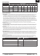
Transmitter
Frequency 2.4GHz
Channels 2
Power supply 4 AA cells
Electronic Speed Control (ESC) DYNS2700
Input Voltage 3-8S LiPo
Constant/Peak Current 100A/650A
Resistance 0.0005 ohm
Programming Port FAN / PRG Port
BEC Voltage 6V/5A, Switch mode
Size 59.5mm (L) × 48mm (W) × 42mm (H)
Weight 173 g
Receiver
Size 37.8mm (L) × 22.5mm (W) × 13mm (H)
Weight 5 Grams
Voltage 4.5V-6.5V
Servo
Voltage 6.0V~7.4V
Output Torque 14 kg-cm @ 6.0V
Operating Speed 0.2sec/60 degrees of travel @ 6.0V
Size 40mm (L) × 20mm (W) × 38.5mm (H)
Motor
Type 4274 Brushless
Turns Kv -- 1600
COMPONENT SPECIFICATIONS
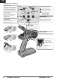
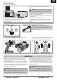
BINDING
Binding is the process of programming the receiver to recognize
the GUID (Globally Unique Identifi er) code of a single specifi c
transmitter. The FCES14000 transmitter and FCES14001 receiver
are bound at the factory. If you need to rebind, follow the
instructions below.
1. Install the transmitter batteries and power OFF the
transmitter.
2. Insert the bind plug into the BIND/CH3 port of the receiver.
3. Connect the battery to the VCC port of the receiver. The
two LEDs will flash indicating BIND mode.
4. Press and hold the BIND button on the transmitter, then
power ON the transmitter.
5. When the LED on the receiver stops flashing after
approximately 5 seconds, the transmitter and receiver are
successfully bound.
6. Release the BIND button on the transmitter and remove the
BIND plug from the receiver.
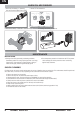
FAILSAFE
In the unlikely event that the radio link is lost during use, the
receiver will drive the servos to their pre-programmed failsafe
positions (normally full brakes and straight steering). If the
receiver is turned on prior to turning on the transmitter, the
receiver will enter failsafe mode, driving the servos to their
preset failsafe positions. When the transmitter is turned on,
normal control is resumed. To set failsafe, follow these steps.
1. Power ON the transmitter.
2. Power on the receiver, the LED will light up.
3. Adjust the transmitter’s throttle until the vehicle stops.
4. Press the ”Setting” button on the receiver. The LED will flash for
3 seconds then go off, indicating FAILSAFE is set.
Failsafe must be set every time the system is bound. Binding will
reset the failsafe setting.
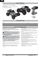
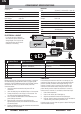
ELECTRICAL LAYOUT
Included Part # Replacement Part # Description
A DYNS1632 DYNS1632
Motor
B Not included
DYNB3804EC, DYNB3854EC, DYNB3810EC,
DYNB3857EC, DYNB3855EC,
14.8V Battery, 15.2V Battery, 7.4V Battery, 15.2V Battery,
7.6V Battery,
C SPMSS6280 SPMSS6280
Steering Servo
D FCES14001 FCES14001
Receiver
E DYNS2700 DYNS2700
Electronic Speed Control (ESC)
E DYNC0166 DYNC0166
EC5 Battery Jumper (use when only one battery is installed)
EC5
EC5
EC5EC5
EC5
EC5
For correct operation, Channels 1
and 2 must be used as shown in the
wiring diagram. The motor can be
disconnected from the ESC at the
connectors in the wiring.
A
B
C
D
E
F
ON/OFF Switch