Horizon Elite™ Ice Machine Installation Instructions for Remote Condensing Unit HCD/HMD/HCF/HMF1010R _ _ HCD/HMD/HCF/HMF1410R _ _ 801 Church Lane • Easton, PA 18040, USA Toll free (877) 612-5086 • +1 (610) 252-7301 www.follettice.
Horizon Elite 1010 series W1 Width D1 Depth H1 Height Electrical 36.25" (91.4 cm) – AJA7490ZXDPN and AWA9490ZXTPN 38.10" (96.8 cm) – all others 25.50" (64.8 cm) – AJA7490ZXDPN and AWA9490ZXTPN 21.50" (54.6 cm) – all others 26.10" (66.3 cm) – AJA7490ZXDPN and AWA9490ZXTPN 28.50" (20.3 cm) – all others single phase – 208-230/60/1 three phase – 208-230/60/3 single phase – 10.7A three phase – 9.9A Horizon Elite 1410 series 36.25" (90.1 cm) – single phase (Tecumseh) 37.75" (95.
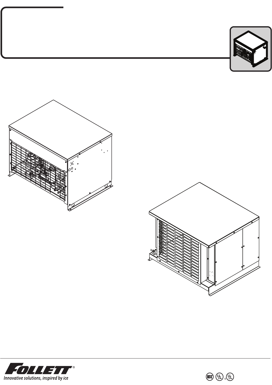
Prior to installation, carefully unpack and inspect the contents of your condensing unit! Site preparation To ensure proper performance, ease of service and warranty coverage, it is critical that you follow the requirements detailed in this manual. If you cannot meet these requirements or have questions, call our technical service group at 877.612.5086 for installation support. 1 2.1 1.1 Condenser Unit Clearances min. 36.00" (91.4 cm) air in exhaust 48.00" (121.9 cm) 24.00" (61.0 cm) 24.00" (61.
2.1 1.2 Condenser installation specifications ➊ 100' max. (30.5 m) CONDENSER UNIT ➍ maximum line rise P-trap required S-trap required ➋ ➊ +35' (+10.7 m) +20' (+6.1 m) Easton Pennsylvania CORPORATION MODEL PART NO SERIAL NO FULL LOAD AMPS VOLTS HZ SINGLE PHASE MOTOR COMPRESSOR THERMALLY PROTECTED REFRIGERANT CHARGE DESIGN PRESSURE HIGH SIDE Stock Module Identification Plate Module No. Product OZ LOW SIDE PSIG 208264 MIN. BRANCH CIRCUIT AMPACITY AMPS MAX.
Condenser installation 2.1 2 Install condensing unit • Level unit • Securely attach base of unit using holes found in base plate • Required rack system capacity at 0 F (-18 C) evaporator (EPR supplied by installer). 1010N: 7,700 Btu/hr (1940 kcal/hr) 1410N: 10,000 Btu/hr (2519 kcal/hr) 2.
2.3 Electrical connections at contactor ELECTRICAL DISCONNECT Single Phase POWER SUPPLY 230-60-1 L3 T3 L2 T2 L1 T1 • Electrical disconnects required within 10' (3 m) for all hard wired connections. • Install in accordance with NEC and local electrical codes.
Refrigeration line installation 3.1 3 Refrigeration line installation: 5/8" suction / 3/8" liquid line (1010, 1410) CAUTION • The installer of the refrigeration line set must be USA Government Environmental Protection Agency (EPA) certified in proper refrigeration handling and service procedures • A qualified person must perform all roof or wall penetration • Do not form unwanted traps in refrigeration lines. A service loop is not considered an oil trap.
Pressure adjustment 4.1 4 Set low-pressure switch - if applicable DIFFERENTIAL ADJUSTMENT SCREW CUT-IN ADJUSTMENT SCREW EXAMPLE 1) Adjust the top LEFT screw until the pointer is set to 10 (the differential). Cut In 20 3.0 2.0 Differential 10 1.0 2) Adjust the top RIGHT screw until the pointer is set to 20 (the cut-in). KG. Cut Out Differential 10 = 10 40 10 30 20 20 40 10 60 80 LBS. 100 LBS. 0 1.0 4.0 Cut In 20 5.5 7.0 KG. CUT OUT IS CUT IN MINUS DIFFERENTIAL Hail hood 5.
3. Install hail hood (5) to brackets using the remaining six screws (6). Note: The bottom hole in the bracket is not used when mounting the hail hood (7). 6 5 7 NOT USED 5.1 1. Install hail hood (Larkin units only) Hail hood comes factory mounted. To remove hood for condenser cleaning, please remove the four (4) hex head screws. Reinstall after cleaning using the same four screws.
Start up and test 6 NOTICE Ice machine MUST be cleaned and sanitized prior to operation! Consult Operation and Service Manual provided with ice machine for cleaning and sanitizing instructions. 6.
REMOTE CONDENSING UNIT 11
Harmony, Horizon, Horizon Elite, Ice Manager, and Vision are trademarks of Follett LLC. Chewblet, RIDE and Follett are registered trademarks of Follett LLC, registered in US. 801 Church Lane • Easton, PA 18040, USA Toll free (877) 612-5086 • +1 (610) 252-7301 www.follettice.