
User Manual
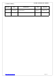
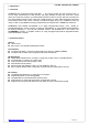
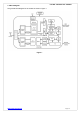
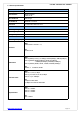
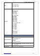
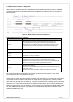
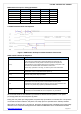
Table Of Contents

FN-LINK TECHNOLOGY LIMITED
http://www.fn-link.com Page10/17
SDIO Interface Power-On Timing Parameters
Symbol MIN Typical MAX Unit
T33ramp’
- - No Limit ms
Toff
250 500 1000 ms
T33ramp
0.1 0.5 2.5 ms
T12ramp
0.1 0.5 1.5 ms
TPOR
2 2 8 ms
Tnon_rdy
1 2 10 ms
3
.5 UART Interface Power-On Sequence
Figure 4. UART Power On Sequence With Hardware Flow Control
UART Interface Power-On Sequence
S
ymbol
D
escription
T33ramp’
3.3V Power Pre-Charge Ramp Up Duration Before Formal Power Up.
We recommend that a 3.3V power-on and then power-off sequence is
executed by the host controller before the formal power on sequence. This
procedure can eliminate host card detection issues when
power ramp up duration is too long, or when a system warm reboot fails.
Toff
The duration 3.3V is cut off before formal power up.
T33ramp
The 3.3V main power ramp up duration.
T12ramp
The internal 1.2V ramp up duration.
TPOR
The duration from when the power-on reset releases and the power
management unit executes power on tasks. A power on reset will detect both
3.3V and 1.2V power ramp up after a predetermined duration.
Tnon_rdy
UART Not Ready Duration.
In this state, the RTL8723BS-VD will not respond to any commands.
We recommend that the card detection procedures are divided into two phases: A 3.3V power
pre-charge phase and a formal power-up phase.
During the 3.3V power pre-charge phase, the power ramp up duration is not limited. The 3.3V power is
cut off and is turned on after the Toff period. The ramp up time is specified in the T33ramp duration.
After main 3.3V ramp up and 1.2V ramp up, the power management unit is enabled by the power ready
detection circuit. The power management unit enables the Bluetooth block. The Bluetooth firmware