
Instructions 2014

1) Remove the sight cover.
2) Turn the sight on so the dot is visible.
3) Make sure the locking screw is locked before firing.
4) Shoot a 3 shot group at a target 10 yards away to get on paper.
5) Loosen the locking screw by turning it counter clockwise one half turn.
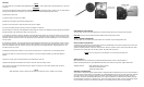
6) Insert either end of the tip of the adjustment tool through the center of the adjustment dial so that the tip protrudes
through the back of the dial and the dial is snug on the tool.
7) To adjust the elevation, insert the adjustment tool with adjustment dial into the slot of the elevation screw. To raise
the point of impact, turn the elevation screw counter-clockwise. To lower the point of impact, turn the elevation screw
clockwise. Note the reference mark on the sight body for the adjustment dial. This will allow you to see how much to
turn the screw.
8) To adjust the windage, insert the adjustment tool with adjustment dial into the slot of the windage screw. To move
the point of impact left, turn the windage screw counter-clockwise. To move the point of impact right, turn the eleva-
tion screw clockwise. Note the reference mark on the sight body for the adjustment dial. This will allow you to see
how much to turn the screw.
9) Adjust the windage and elevation so your group is centered and 2 to 3 inches low. Lock the locking screw.
10) Since the sight can only be zeroed for one distance, zero for the farthest distance you will shoot with this
firearm.
11) Shoot a 3 shot group at the final distance you determined in step 10.
12) Adjust the windage and elevation until zero is achieved. Lock the locking screw.
13) If zeroing is accurate, fire three more shots to confirm. If zeroing is not accurate, repeat steps 11 and 12
until zeroing is complete.
NOTE
After initial firing, check to ensure that the mount and sight are secure. Tighten as necessary.
ZEROING
NOTE
The STS Sight has a rectangular sized adjustment area of 120 in. wide x 180 in tall at 100 yds (304.8 cm x 457.2 cm
at 100 m).
WARNING
The lock screw MUST be loosened before adjusting the elevation or windage screws. Failure to do so could result in
damage to the adjustment mechanism. The lock screw MUST be locked (tightened) before firing.
WARRANTY INFORMATION
This product is warranted against original defects in material and/or manufacturing for one year. This warranty is
void if the unit has been abused, disassembled, or modified/tampered with in any way from its original configura-
tion. This warranty does not apply to defects caused by normal wear and tear, improper handling, incorrect
installation, accidents, alterations/modifications to the original configuration, repairs made by unauthorized par-
ties, aftermarket accessories, or abnormal use. Due to the fragile nature of glass, the lens is specifically exclud-
ed from warranty coverage. This warranty is limited to the original purchaser and is not transferable.
MAINTENANCE PROCEDURES
The STS sight requires very little maintenance. Periodic cleaning of the lens and sight is encouraged.
CAUTION The lens can be scratched if dirt is wiped across the lens with a cloth.
SIGHT CLEANING PROCEDURE
The STS sight can be washed using clean water and a soft cloth. Dry thoroughly before use.
LENS CLEANING PROCEDURE
1) Remove large particles from exposed lens surfaces by first blowing on the surfaces. Blow as much dust and
dirt as possible from the exposed lens surfaces.
2) When all visible particles of dust and dirt have been removed, moisten a piece of lens tissue with lens clean-
ing solution, then gently wipe over the lens surface. Dry with clean lens tissue.
NOTE If the lens fogs over in cold weather, use a lens tissue to wipe clear.
SERVICE POLICY
FNH USA products are serviced by the FNH USA Product Service Center in Arnold, Missouri.
Please call (800) 635-1321 or (703) 288-1292 extension 122 to discuss any product repair requirement.
Shipping Address: FNH USA Product Service Center
3005 Arnold Tenbrook Road
Arnold, MO 63010-4728