
Instructions 2014

FNH USA, LLC
PO Box 697
McLean, VA 22101
(703) 288-1292, extension 122
www.fnhusa.com
FNH-IB-STS-033009
PLEASE read instructions before operating or
installing this sighting system.
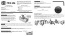
PACKAGE CONTENTS:
1 - STS Sight (optional - attached to PS90 mount)
1 - Cover
1 - Instruction Manual
1 - Adjustment Tool
1 - Adjustment Dial
Instruction Manual
© FNH USA, LLC
Congratulations! You are now the owner of the most
advanced reflex sighting system available. You have
displayed excellent judgement in your purchase, and
you will be rewarded with unparalleled performance.
Use it with pride, but please familiarize yourself with the
system first.
STS - Small Tactical Sight
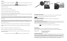
DESCRIPTION OF MAJOR COMPONENTS
INTENSITY SWITCH
Used to set the intensity (Brightness) of the dot or turn
the dot off. Sliding the switch to the far left position
(OFF) will turn the dot off. Sliding the switch to the mid-
dle position (AT) will turn the dot on and the intensity
will be controlled automatically. Sliding the switch to the
far right position (M) will manually set the intensity to
full bright and will not be adjusted automatically.
NOTE
Installing the protective cover does not turn the sight
off.
WINDAGE ADJUSTMENT SCREW
Used when zeroing weapon. Turning the windage adjustment screw clockwise
moves the point of impact right. Turning the windage adjustment screw counter-
clockwise moves the point of impact left.
LOCK SCREW
Used to lock the elevation and windage adjustment mechanism once the sight has been zeroed to the weapon.
Turning the lock screw counter-clockwise one half turn will loosen the screw and allow elevation and windage adjust-
ments to be made. Turning the lock screw clockwise until firmly snug will lock the elevation and windage adjustments
in their current location.
ELEVATION ADJUSTMENT SCREW
Used when zeroing weapon. Turning the elevation adjustment screw clockwise moves the point of impact down.
Turning the elevation adjustment screw counter-clockwise moves the point of impact up.
BATTERY REPLACEMENT
1) Remove the sight cover.
2) Remove the battery tray by using the adjustment tool to pry it open from the sight body. Ease the tip of the
tool behind the tab on the battery tray. Push the tip all the way down to the base of the tab and pry the tray open
and pull it out of the sight. (Make sure to hold your hand over the tray to catch it when it releases from the sight)
3) Insert battery into the battery tray with positive (+) side facing up.
4) Insert the battery tray with battery into the sight body until it detents into the fully inserted position.
(The battery tray should be flush with the side of the sight body)
ADJUSTMENT
TOOL
The adjustment tool has three uses.
1)Used to loosen and tighten the lock screw.
2)Used to adjust the windage and elevation adjustment screws.
3)Used to pry open the battery tray.
ADJUSTMENT DIAL
Used to indicate how much the windage or elevation is being
adjusted. Install on the end of the adjustment tool and use the
witness marks on the sight body to determine the value of
adjustment.
NOTE
Each division = 1moa or 1" at 100 yds.