
Instructions 2011

ADJUSTING FOR ELEVATION / VERTICAL CORRECTION
Locate the center of the last fired group on the target. Carefully measure the
vertical distance from the center of the group to the center of the aiming mark.
Record this measurement for reference.
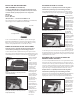
Insert the front sight post wrench (FNH USA Product # 9350033B) over the front
sight post of the emergency backup iron sights, carefully mating the flats on
the front sight post with the flats on the shaft of the front sight post wrench
(Figure 8). Turning the front sight post wrench clockwise lowers the front sight
post and raises the
point of bullet impact.
Turning the front
sight post wrench
counterclockwise
raises the front sight
post and lowers the
point of bullet impact.
Each 90-degree
(quarter-turn) of
rotation of the front
sight post with the
front sight post
wrench moves the
point of bullet impact
about 3"/ 7.5cm
(6MOA) at a distance of 50 meters. By a process of trial and error, continue to
shoot three to five shot groups to further refine the front sight post sight
adjustment until the center of the group fired is exactly aligned vertically with
the aiming mark.
Upon completion of every group fired, verify the firearm is
completely unloaded and the magazine is removed before
performing any adjustment procedures.
Do not remove the front sight post from the M1913 USG Rail. Reinstallation
of the front sight post may seriously damage the threads in the aluminum
rail body.
INSTALLATION OF AFTERMARKET OPTICAL OR
ELECTRONIC SIGHT SYSTEM ON THE M1913 USG RAIL
Verify the firearm is completely unloaded and the magazine is
removed before performing any of the following procedures.
Follow the manufacturer’s installation instructions as supplied with the optical
or electronic sight system. Make sure that all mounting rings or other mounting
devices are fully compatible with US/NATO Mil. Std. M1913 base rails.
After initial installation, follow the manufacturer’s adjustment and zeroing
instructions supplied with the optical or electronic sighting system or other
accessory at a suitable range facility, using the same type of ammunition
intended for actual use. Note these zero adjustments in your owner’s manual
for future reference.
Upon completion of every group fired, verify the firearm is
completely unloaded and the magazine is removed before
performing any adjustment procedures.
Remember that any time an optical or electronic sighting system is removed
from and/or reattached to the firearm, the zero should be re-verified at a
suitable range facility, using the same type of ammunition intended for
actual use.
Fire an initial zeroing group using the emergency backup iron sights. Using
suitable eye and hearing protection, load and fire three to five rounds from a
stable, supported firing position at a clearly defined aiming mark on a target
backing large enough to register all hits. Take your time and concentrate on the
careful aiming and precise firing of each shot. Make sure you head is in the
same position on the stock for each shot. Make sure the front sight is centered
in the aperture in the rear of the rail, and both are exactly the same position in
relationship to the aiming mark for each shot.
Upon completion of every group fired, verify the firearm is
completely unloaded and the magazine is removed before
performing any adjustment procedures.
ADJUSTING FOR WINDAGE / HORIZONTAL CORRECTION
Locate the center of the fired group on the target. Carefully measure the
horizontal distance from the center of the fired group to the center of the
aiming mark. Record this measurement for reference.
Windage (horizontal) adjustments to point of bullet impact are made by turning
the rail adjustment bushing clockwise or counterclockwise, thus pivoting the
entire rail around the rear rail mounting screw.
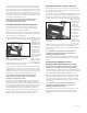
Using the 3mm Allen wrench, slightly loosen the countersunk hex socket locking
screw in the threaded rail adjustment bushing. If the first group fired impacts
to the right of the
aiming mark, insert
the Sight Adjustment
Tool through the access
hole located at the
right front side of the
M1913 rail (Figure 7),
and turn the rail
adjustment bushing
clockwise to move the
point of bullet impact
to the left. If the
center of the group
impacts to the left of
the aiming mark, use
the Sight Adjustment Tool to turn the rail adjustment bushing counterclockwise
to move the point of bullet impact to the right.
Each 90-degree (quarter turn) of rotation of the rail adjustment bushing with
the Sight Adjustment Tool moves the point of bullet impact about 9.5"/ 24cm
(19 MOA) at a distance of 50 meters. By a process of trial and error, continue to
shoot three to five shot groups to refine the sight adjustments until the center
of the group fired is exactly aligned horizontally with the aiming mark.
Upon completion of every group fired, verify the firearm is
completely unloaded and the magazine is removed before
performing any adjustment procedures.
When the group is horizontally aligned with the aiming mark, insert the Sight
Adjustment Tool into the rail adjustment bushing, being very careful not to
rotate the adjustment tool or bushing. Insert the 3mm Allen wrench through the
hole in the center in the adjustment wrench shaft and into the locking screw.
Use the Sight Adjustment Tool to prevent any movement of the rail adjustment
bushing while tightening the locking screw to maintain this adjustment.
After you have tightened the locking screw in the rail adjustment bushing, also
tighten the locking screw located at the top rear of the rail to prevent any
further rail movement in the upper receiver/barrel support assembly.
FIGURE 8
Adjust the front sight post elevation using the front
sight post wrench.
FIGURE 7
Use the 3mm Allen wrench and the sight adjustment tool to
lock the windage adjustment bushing in place.
FNHUSA_08_10_15