
Instructions 2011

INSTALLATION OF THE M1913 USG RAIL
Verify the firearm is completely unloaded and the magazine is
removed before performing any of the following procedures.
Insert the M1913 USG Rail into the top of the upper receiver/barrel support
assembly, with the front post of the emergency backup iron sights toward the
muzzle end of the
firearm (Figure 4).
Align the hole located
at the top rear of the
rail insert with the
matching hole in the
upper receiver/barrel
support assembly.
Insert the locking
screw you removed
from the factory
optical sight using
the 3mm Allen
wrench. Do not
tighten the locking
screw yet, to allow for
final adjustments to
the rail section.
Using the 3mm Allen
wrench, insert the
locking screw you
removed from the
factory optical sight
through the access
hole located at the
right front side of the
rail, then through the center of the threaded rail adjustment bushing and into
the matching threaded hole in the left side of the upper receiver/barrel support
assembly (Figure 5). Do not fully tighten the locking screw yet, to allow for final
adjustments to the rail section.
ADJUSTMENT OF M1913 USG RAIL FOR ZEROING THE
EMERGENCY BACKUP IRON SIGHTS
It is critical to adjust the M1913 USG Rail into exact alignment with the barrel
of the firearm. This zeros the emergency backup iron sights built into the rail
and allows use of the full range of internal adjustments in aftermarket optical
or electronic sighting systems. All zeroing of the emergency backup iron sights
and the optical or electronic sighting system should be conducted at a suitable
range facility, using the same type of ammunition intended for actual use.
Verify the firearm is completely unloaded and the magazine is
removed before performing any of the following procedures.
Insert the PS90 / P90 Sight Adjustment Tool (FNH USA Product # 3058490010)
through the access hole located at the right front side of the M1913 rail,
aligning the two teeth on the end of the adjustment wrench shaft with the
matching notches in
the threaded rail
adjustment bushing
(Figure 6). Looking
down at the top of
the rail, carefully
center the M1913
rail between both
walls of the upper
receiver/barrel
support assembly.
M1913 USG RAIL INSTRUCTIONS
(FNH USA PRODUCT # 3819400120)
Consult your FNH USA owner’s manual for full information on the
safe handling and operation of your FN firearm. If you do not have
an owner’s manual, you may request one at no charge from:
FNH USA
P.O. Box 9424
McLean, VA 22102
(855) 536-4872 or customerservice@fnhusa.com
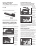
This package includes the PS 90 M1913 rail (FNH USA Product # 3819400120)
and front sight post wrench (FNH USA Product # 9350033B).
In order to install the M1913 rail, you MUST also purchase the PS90 Sight
Adjustment Tool (#3058490010) to remove the factory sight and install the
M1913 rail. If you have purchased your PS90
®
with the M1913 rail already
installed, this Sight Adjustment Tool is included with the carbine.
REMOVAL OF THE FACTORY OPTICAL SIGHT ASSEMBLY
Verify the firearm is completely unloaded and the magazine is
removed before performing any of the following procedures.
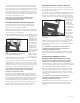
Locate the threaded elevation adjustment bushing on the upper rear of the
factory optical sight assembly, just behind the rear sight window (Figure 2). Use
the 3mm Allen wrench to remove the countersunk hex socket locking screw from
the center of the
elevation adjustment
bushing and put it
aside.
Locate the threaded
windage adjustment
bushing on the right
front of the upper
receiver/barrel
support assembly,
below the front sight
window (Figure 3).
Use the 3mm Allen
wrench to remove the
locking screw from
the center of the
adjustment bushing
and put it aside.
The factory optical
sight assembly can
now be removed from
the upper receiver/
barrel support
assembly. Store the
factory optical sight
assembly in a
cool, dry, dust-
free location.
FIGURE 2
Removing the countersunk hex socket locking screw from the
elevation adjustment bushing.
FIGURE 4
Insert the M1913 USG rail into the top of the upper receiver.
FIGURE 5
Insert the locking screw into the rail adjustment bushing.
FIGURE 6
Insert the Sight Adjustment Tool into the rail adjustment bushing.
FIGURE 3
Removing the countersunk hex socket locking screw from the
windage adjustment bushing.
M1913 Rail
Front Sight Post Wrench