FN 509 ® Series ...
Important operating instructions for: FN 509® AUTOLOADING PISTOLS If you have any questions or comments regarding your new firearm, please contact us. FN Service Center 797 Old Clemson Rd Columbia, SC 29229 1-800-635-1321 customerservice@fnamerica.com www.fnamerica.com Please use the space below to record information about your new firearm.
CONTENTS PAGE 1. Foreword ..........................................................2 2. Basic safety rules ...........................................4 11.2 Reassembly from the field stripped condition ...................39 3. Ammunition ...................................................11 11.3 Backstrap removal .............................41 4. Dry firing & “dummy” rounds ......................13 11.3.1 Backstrap installation ........42 5. Nomenclature .............................................
1. FOREWORD ALWAYS KEEP THIS MANUAL WITH YOUR FIREARM. INCLUDE IT WITH THE PISTOL WHEN IT CHANGES OWNERSHIP OR WHEN IT IS LOANED OR PRESENTED TO ANOTHER PERSON.
IT IS YOUR RESPONSIBILITY TO KNOW AND ABIDE BY FEDERAL, STATE AND LOCAL LAWS GOVERNING THE SALE, TRANSPORTATION, OWNERSHIP, POSSESSION, AND USE OF FIREARMS IN YOUR AREA. CALIFORNIA STATE WARNING, SAFETY AND WARRANTY NOTES According to state law, California requires that firearms manufacturers, distributors and retailers include conspicuous, specific warnings with firearms sold in that state.
2. BASIC SAFETY RULES READ THIS MANUAL BEFORE HANDLING YOUR FIREARM. WARNING: FIREARMS CAN BE DANGEROUS AND CAN CAUSE SERIOUS INJURY, DAMAGE TO PROPERTY OR DEATH, IF HANDLED IMPROPERLY. THE FOLLOWING SAFETY RULES ARE IMPORTANT REMINDERS THAT AS A FIREARMS OWNER SAFETY IS YOUR RESPONSIBILITY. THERE IS NO EXCUSE FOR CARELESS OR ABUSIVE HANDLING OF ANY FIREARM. HANDLE THIS FIREARM AND ALL OTHER FIREARMS WITH RESPECT FOR THEIR POWER AND POTENTIAL DANGER AT ALL TIMES. 1.
not fire even if the “safety” is in the on “safe” position. Mechanical “safeties” merely aid safe gun handling and are no excuse for pointing your firearm’s muzzle in an unsafe direction. Some firearms do not have a mechanical safety. Many target firearms, lever-action firearms and pistols do not have manual “safety” mechanisms. Therefore, it is critical to read and understand the owner’s or operator’s manual for every firearm that you use, which explains the safe operation of the firearm.
fragmentation of the bullet which can result in the bullet striking an unintended target. 6. WHENEVER YOU HANDLE ANY FIREARM, OR HAND IT TO SOMEONE, ALWAYS OPEN THE ACTION IMMEDIATELY AND VISUALLY CHECK THE FIREARM’S CHAMBER AND MAGAZINE TO MAKE CERTAIN THAT THE FIREARM IS COMPLETELY UNLOADED. Completely unload your firearm as described in Section 6. Make certain the firearm does not inadvertently contain any ammunition. Remember, merely removing the magazine does not mean the chamber is unloaded.
Store and carry your firearm so debris does not accumulate in the working parts. Clean and oil your firearm following the instructions provided in this manual after each use to prevent corrosion damage or accumulation of debris. Make sure that no obstructions remain in the barrel. Firing the pistol with an obstruction in the barrel can cause extensive damage to your firearm and serious injury to yourself and others.
Always wear appropriate eye protection when disassembling and cleaning your pistol to prevent the possibility of springs, springtensioned parts, solvents or other agents from contacting your eyes. 11. AVOID DROPPING FIREARMS OR SHOOTING FROM UNSTABLE POSITIONS. Shooting from unstable positions is dangerous. Doing so increases the risk of falling or dropping the firearms. The following rules should always be observed.
instructions in section 11.1 and inspect the barrel for obstructions before shooting. Never inspect the barrel while the firearm is loaded or prior to complete field stripping. Mud, snow and an infinite variety of other objects may inadvertently lodge in a barrel bore. If an obstruction is seen, no matter how small it may be, clean the bore with a cleaning rod and patch as described in section 12.1 of this manual.
Closely supervise newcomers to the shooting sports. Encourage enrollment in firearm and shooting safety courses. 17. NEVER DRINK ALCOHOLIC BEVERAGES OR TAKE JUDGEMENT/REFLEX IMPAIRING MEDICATION OR DRUGS BEFORE OR DURING SHOOTING. Your vision, motor skills and judgment could be dangerously impaired, making your gun handling unsafe to you and to others. 18. READ AND HEED ALL WARNINGS IN THIS OWNER’S MANUAL, ON AMMUNITION BOXES AND WITH ALL ACCESSORIES THAT YOU INSTALL ON YOUR FIREARM.
Never fire the pistol upon purchase without first inspecting cleaning and lubricating it before use. Pay special attention that all foreign material is removed from the bore of the barrel to prevent an unsafe condition. 3.
CAREFULLY INSPECT EACH CARTRIDGE BEFORE IT IS LOADED IN THE MAGAZINE. BE CERTAIN THE CARTRIDGE CASE IS NOT SPLIT OR DEFORMED AND THAT THE CARTRIDGES DO NOT POSSESS ANY OTHER DENTS OR DEFECTS. For best results, use new factory manufactured ammunition from a reputable manufacturer. Primers, powder, cartridge cases and bullets can deteriorate with time and cause damage to the firearm or injury to the shooter or others.
If you have concerns about the compatibility of a particular ammunition type with your FN pistol, contact FN customer service before using any such ammunition. 4. DRY FIRING & “DUMMY” ROUNDS Dry firing is defined as firing a firearm with no ammunition in the chamber. Occasional dry firing of your FN 509 and for disassembly is acceptable. Regularly dry firing your FN 509 pistol for practice or training may result in damage to the striker.
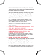
FIGURE 1 Ambidextrous Slide Stop Loaded Chamber Indicator Ejection Port Accessory Rail Frame Assembly Curved Backstrap Magazine Right view of the FN 509 pistol (non-manual safety model shown). Front Sight Takedown Lever Ambidextrous Slide Stop Rear Sight Muzzle Slide Optional Ambidextrous Manual safety Lever Ambidextrous Magazine Release Grip Left view of the FN 509 pistol (manual safety model shown).
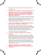
FIGURE 2 Loaded Chamber Indicator Ejection Port Ambidextrous Slide Stop Accessory Rail Frame Assembly Curved Backstrap Right view of the FN 509 Tactical pistol (non-manual safety model shown). Front Sight Takedown Lever MRD Screws Ambidextrous Slide Stop MRD Cap Cap, Threaded Barrel Slide Ambidextrous Magazine Release Grip Left view of the FN 509 Tactical pistol (non-manual safety model shown).
BEFORE HANDLING, STORING OR TRANSPORTING YOUR PISTOL, FOLLOW THESE PROCEDURES TO ENSURE THE PISTOL IS UNLOADED. ALWAYS KEEP THE MUZZLE OF YOUR FIREARM POINTED IN A SAFE DIRECTION. KEEP YOUR FINGERS AWAY FROM THE TRIGGER UNTIL READY TO SHOOT. FAILURE TO FOLLOW THESE WARNINGS COULD RESULT IN SERIOUS INJURY OR DEATH. 1. Depress the magazine release to eject the magazine.
4. Release the slide by pushing downward on the slide stop or by pulling rearward on the slide to disengage the slide stop and then let the slide move forward under control (Figure 6). FIGURE 5 FIGURE 6 Empty chamber. Slide released. 5. Ensure that the magazine is empty. If the magazine is not empty, unload it as described in Section 6.4. Unload any spare magazines. CAUTION: THE RECOMMENDED CARRY CONDITION OF YOUR PISTOL IS WITH THE CHAMBER EMPTY.
6. LOADING AND UNLOADING LOAD THE CHAMBER ONLY WHEN READY TO USE THE PISTOL. WHENEVER A LIVE ROUND IS IN THE CHAMBER THE PISTOL CAN FIRE, EVEN IF THE MAGAZINE IS EMPTY OR HAS BEEN REMOVED. WHEN LOADING YOUR PISTOL ALWAYS KEEP THE MUZZLE POINTED IN A SAFE DIRECTION AND KEEP YOUR FINGERS AWAY FROM THE TRIGGER. FAILURE TO FOLLOW THESE WARNINGS COULD RESULT IN SERIOUS INJURY OR DEATH.
If the magazine to be loaded is still in the pistol, depress the magazine release and remove the magazine from the pistol. Hold the magazine in one hand. With the other hand, place a cartridge on the magazine follower or on the cartridge case of the previously loaded round in the magazine in front of the feed lips at the top of the magazine. Press the cartridge down into the FIGURE 7 magazine body and slide the cartridge under the feed lips until it is seated fully inside the magazine body.
6.2 LOADING THE PISTOL WHEN LOADING YOUR PISTOL, ALWAYS KEEP THE MUZZLE POINTED IN A SAFE DIRECTION AND KEEP YOUR FINGERS AWAY FROM THE TRIGGER. ALWAYS CLOSE THE SLIDE BEFORE INSERTING A LOADED MAGAZINE IF YOU DO NOT WISH TO IMMEDIATELY CHAMBER A CARTRIDGE. FAILURE TO FOLLOW THESE WARNINGS COULD RESULT IN SERIOUS INJURY OR DEATH. 1. Before loading, ensure that the chamber of the pistol is empty and the pistol does not contain a magazine.
FIGURE 10 FIGURE 11 Retract slide. Depress slide stop lever. 3. With the muzzle pointed in a safe direction and your fingers away from the trigger, hold the pistol in your firing hand and pull the slide fully rearward with the other hand and release the slide, which will return under the force of the recoil spring (Figure 10-11). You can also press down on the slide stop to allow the slide to move forward and chamber a cartridge if the slide is locked to the rear.
6.3 UNLOADING WHILE UNLOADING THE PISTOL, ALWAYS KEEP THE MUZZLE POINTED IN A SAFE DIRECTION AND KEEP YOUR FINGERS AWAY FROM THE TRIGGER. IF YOUR PISTOL IS EQUIPPED WITH A MANUAL SAFETY, THE SAFETY SHOULD BE IN THE ENGAGED POSITION. WHEN UNLOADING, IT IS VITAL THAT YOU REMOVE THE MAGAZINE FROM YOUR PISTOL SO THAT A CARTRIDGE IS NOT CHAMBERED WHEN YOU CLOSE THE SLIDE. FAILURE TO FOLLOW THESE WARNINGS COULD RESULT IN SERIOUS INJURY OR DEATH. 1. Press the magazine release and remove the magazine.
3. Inspect the chamber and magazine well to ensure no cartridge is present. Remember, merely removing the magazine does not mean the chamber is unloaded (Figure 14). 4. The slide should be left in the open position until ready to load or when putting the pistol away. Empty chamber. To release the slide, pull rearward on the slide to disengage the slide stop or press down on the slide stop to allow the slide to move forward (Figure 15-16). FIGURE 14 FIGURE 15 FIGURE 16 Retract slide.
6.4 UNLOADING THE MAGAZINE 1. Depress the magazine release and remove the magazine (Figure 17). 2. Unload the pistol and place it in a safe condition as detailed in Section 6.3. 3. Strip the top cartridge from the magazine by pushing forward on the rim of the cartridge and slide the cartridge out from under the feed lips. When the cartridge is removed the remaining cartridges will move up in the magazine. Continue removing the cartridges in this manner until the magazine is empty.
7. FIRING WHEN FIRING, THE SLIDE MOVES REARWARD PAST THE BACK OF THE FRAME. TO PREVENT THE SLIDE FROM CAUSING INJURY IN ITS REARWARD MOVEMENT WHEN SHOOTING, KEEP THE PISTOL AWAY FROM THE EYES OR FACE. KEEP YOUR HAND IN A POSITION WHERE THEY CANNOT BE HIT BY THE SLIDE. FAILURE TO FOLLOW THIS WARNING COULD RESULT IN SERIOUS INJURY. 1. Load a cartridge into the chamber as detailed in Section 6.2. 2.
7.1 RELOADING DURING FIRING NEVER CHAMBER A CARTRIDGE UNLESS USE OF THE PISTOL IS IMMINENT. ALWAYS KEEP THE MUZZLE POINTED IN A SAFE DIRECTION. MAKE SURE YOUR FINGERS ARE SAFELY AWAY FROM THE CHAMBER WHEN THE SLIDE IS RELEASED TO AVOID PINCHING THEM WHEN THE SLIDE CLOSES. FAILURE TO FOLLOW THESE WARNINGS COULD RESULT IN SERIOUS INJURY OR DEATH. After firing the last cartridge with the magazine inserted, the slide will remain in the open position.
3. Release the slide by pulling rearward on the slide to disengage the slide stop and allow the slide to move forward and chamber a cartridge. You can also press down on the slide stop to allow the slide to move forward and chamber a cartridge. When the slide closes, the pistol is loaded and ready to fire. You may now continue firing (Figure 23-24). FIGURE 23 FIGURE 24 Retract slide. Depress slide stop lever.
8. FUNCTION OF THE FN 509 The FN 509 is a semi-automatic, locked-breach pistol. With the chamber and magazine loaded, the pistol will fire a single shot each time the trigger is pulled until the magazine and chamber are empty. The slide will remain locked to the rear after the last cartridge is fired. 8.1 FIRING CYCLE When the trigger is pulled the striker block and trigger safety are disconnected and the striker is released to move forward and strike the primer of the loaded cartridge, firing the pistol.
FIGURE 25 Striker block. • The drop safety prevents the sear from moving down out of engagement with the striker unless the trigger has been pulled to the rear (Figure 26). • The trigger disconnect safety is actuated when the disconnect cam is pushed out of alignment with the sear preventing the sear from releasing the striker. This safety feature prevents the pistol from firing out of battery (Figure 27). FIGURE 26 FIGURE 27 Drop safety. Trigger disconnect.
• The trigger safety remains engaged unless the shooter’s finger is on the trigger and blocks the rearward movement of the trigger, preventing the trigger from moving rearward under inertia should the pistol be dropped (Figure 28). FIGURE 28 Trigger safety. 9.2 MANUAL SAFETY (APPLICABLE ONLY TO PISTOLS WITH A MANUAL SAFETY) FIGURE 29 FIGURE 30 Safety engaged. Safety disengaged.
the rear of the frame. When the safety levers are moved to the up position, the safety is engaged and blocks the movement of the sear carrier and trigger assembly. When the safety levers are moved down the red dot indicating that the pistol will fire is exposed and the firing mechanism is free to operate. The safety lever is retained in the selected position by a detent and will snap into location when engaged or disengaged.
9.3 AMBIDEXTROUS SLIDE STOP FIGURE 31 The FN 509 slide stop is fully ambidextrous meaning that the control levers are located on both sides of the frame within easy reach of the thumb of the shooting hand and protected from unintentional activation by a guard located in front of and below the slide stop lever. The Slide stop lever. slide stop is automatically engaged when the last shot from a magazine is fired or the slide is retracted with an empty magazine in the pistol.
9.5 LOADED CHAMBER INDICATOR FIGURE 33 The loaded chamber indicator is located on the right side of the slide just behind the ejection port. When a cartridge is present in the chamber, the extractor is deflected by the case exposing a red dot on the slide directly above the slide stop and providing a tactile indication that the Loaded chamber indicator. chamber is loaded when a finger is placed on the wide groove at the front of the rear slide serrations on the right side of the pistol (Figure 33).
NOTE: Some jurisdictions limit the magazine capacity. All FN pistols intended for sale in those jurisdictions will be shipped with magazines not exceeding the specified number of rounds in compliance with local or state law. Verify the capacity of your magazine before loading it in your pistol to avoid violating local laws in these FIGURE 34 jurisdictions. 9.
Note: The FN 509 has been tested to ensure safe operation. The reliability of the pistol may be affected by the installation of a suppressor or muzzle device. FIGURE 36 9.9 INTERCHANGEABLE BACKSTRAPS The FN 509 has been designed to use interchangeable backstraps that allow the pistol to be adapted to fit your hand better (Figure 36). Backstraps provided vary by model. Interchangeable backstraps. 9.
The sights of the FN 509 should be aligned with the top of the front sight even with the top of the rear sight and an equal gap between the rear sight and the sides of the front sight. The point of impact will be at the top of the front sight when the sights are properly aligned. The dots provided on the sights are intended as an aid in low light conditions and provide a less precise but faster sight alignment. If installing and using an optical sight, the optic must be zeroed for accurate targeting.
FIGURE 38 FIGURE 39 Empty chamber. Lock slide open. 3. Remove the thread protector or muzzle device if the pistol is equipped with a threaded barrel (Figure 40). 4. Rotate the takedown lever approximately 100 deg. clockwise (Figure 41). 5. While holding the slide with one hand, release the slide from the slide stop and ease it forward (Figure 42). FIGURE 40 Rotate thread protector counter clockwise for removal. FIGURE 41 FIGURE 42 Takedown lever rotated. Release slide.
THE PISTOL MUST BE COMPLETELY UNLOADED TO PERFORM STEP 5. FAILURE TO FOLLOW THIS WARNING COULD RESULT IN SERIOUS INJURY OR DEATH. 5. While keeping the rear of the slide and rear of the frame in alignment, point the muzzle in a safe direction and press the trigger to release the striker. The slide will move forward slightly when released (Figure 43). 6. After releasing the striker, you can remove the slide by pulling the slide forward and away from the frame.
7. Hold the slide upside down, grasp the small spring of the recoil spring assembly then lift the recoil spring assembly up and out of the slide (Figure 45). 8. Remove the thread protector or muzzle device if the pistol is equipped with a threaded barrel 9. Grasp the barrel by its lug, lift it up and around the extractor and slide the barrel rearward out of the slide (Figure 46). This level of disassembly is sufficient to perform a thorough cleaning.
3. Place the large end of the recoil spring assembly against the recess in the front of the slide. Compress the recoil spring assembly and slide the back of the recoil spring guide onto the recess until centered on the front of the barrel lug (Figure 49). 4. Guide the slide and barrel Align recoil spring. assembly onto the frame and pull the slide to its rearmost position and lock the slide to the rear using the slide stop (Figure 50). 5.
6. Release the slide and allow it to travel forward. Test the functions of the pistol to ensure the slide stop, trigger, magazine release and manual safety, if provided, are functioning correctly (Figure 52). The pistol is now fully reassembled and is ready to be loaded and fired. FIGURE 52 Assembled pistol. 11.3 BACKSTRAP REMOVAL 1. Using a small 5/64" roll pin punch, push out the backstrap retaining pin (Figure 53). FIGURE 53 FIGURE 54 Backstrap pin removal. Backstrap removal. 2.
11.3.1 BACKSTRAP INSTALLATION 1. Slide the backstrap up the dovetail onto the rear of the frame (Figure 55). 2. Press the backstrap into position closing the gap between the top of the backstrap and grip. Ensure the retaining pin hole in the backstrap is aligned with the slot in the dovetail in the frame (Figure 56). FIGURE 55 FIGURE 56 Backstrap installation. Seated backstrap. 3. Using the back of a punch or a hard surface push the retaining pin into the backstrap.
11.4 MAGAZINE DISASSEMBLY CAUTION: THE MAGAZINE SPRING IS UNDER TENSION. WEAR EYE PROTECTION AND KEEP THE BOTTOM OF THE MAGAZINE POINTED IN A SAFE DIRECTION. 1. Depress the floor plate catch through the hole in the bottom of the magazine floor plate. Slide the floor plate forward and off the magazine body. Capture the magazine spring and floor plate catch with your hand as the base plate is removed (Figure 58-59). FIGURE 58 FIGURE 59 Depress floor plate catch. Slide base plate foreward. 2.
11.4.1 MAGAZINE REASSEMBLY FIGURE 61 1. If removed, assemble the follower on to the magazine spring. 2. Insert the magazine spring and follower into the magazine body with the angle of the follower matched to the angle of the top of the magazine (Figure 61). 3. Using the floor plate catch with the tab protruding down (away from the magazine spring) compress the magazine spring into the magazine body until the spring and floor plate catch are inside of the magazine body (Figure 62). 4.
5. Ensure that the retaining tab of the floor plate catch protrudes into the magazine floor plate and prevents it from sliding off the magazine. If the floor plate catch does not align, tap the magazine against your hand to move the floor plate catch into location (Figure 64). FIGURE 64 Confirm floor plate installation. NOTE: Disassembly beyond the instructions provided is not necessary or recommended. Further disassembly should only be performed by FN authorized personnel. 11.
To install a different optic or slide cap: 1. Loosen and remove the two screws holding the optic or slide cap to the slide of the pistol by turning the screws counter clock-wise (Figure 66). 2. Remove the optic or slide cap, MRD plate and o-ring (Figure 67 & 68). FIGURE 67 FIGURE 66 FIGURE 68 3. Inspect and clean the mounting surface on the top of the slide. 4. Select the appropriate MRD plate and screws to match the optic to be installed.
7. Place the MRD plate in the MRD plate cut, sandwiching the o-ring between the slide and plate (Figure 70). FIGURE 69 8. Set the optic or slide cap on top of the slide and MRD Plate. If your optic requires an MRD insert to be installed under the sight, it should be installed at this time (Figure 71 & 72). 9. Start both mounting screws and tighten them down clock-wise with finger pressure with the provided T10 Torx wrench. FIGURE 70 FIGURE 71 FIGURE 72 NOTE: Do not use threadlocker.
Many optics will allow for use of the existing iron sights. If the optic that you have chosen allows this functionality, the optic can be adjusted to match the point of impact of the iron sights closely by adjusting the aiming point of the optical sight to coincide with the aligned iron sights.
AND USE WILL RESULT IN DAMAGE TO THE SUPPRESSOR OR MUZZLE DEVICE AND PISTOL, AND COULD RESULT IN INJURY TO THE SHOOTER OR THOSE NEARBY. THE BORE OF THE SUPPRESSOR OR MUZZLE DEVICE MUST ALIGN WITH THE BORE OF THE BARREL. IF THE PISTOL IS FIRED WITH THE SUPPRESSOR OR MUZZLE DEVICE MISALIGNED THE SUPPRESSOR OR MUZZLE DEVICE WILL BE DAMAGED, THE PISTOL MAY ALSO BE DAMAGED AND COULD RESULT IN INJURY TO THE SHOOTER OR THOSE NEARBY.
3. Thread the suppressor or muzzle device on to the barrel and tighten it following the manufacturers recommendations. Check to ensure that the bore of the suppressor aligns with the bore of the barrel and nothing blocks the path of the bullet (Figure 74). FIGURE 74 The pistol can now be fired with the suppressor or muzzle device installed. If a suppressor is attached to the barrel without a Nielsen device, the pistol can be safely fired but will not cycle properly.
2. Pull the magazine catch spring up until it is above the magazine release, using a punch to catch the top loop of the spring. NOTE: The spring does not need to be removed from the frame to remove the magazine release, removing the spring makes reassembly more difficult. 3. Slide the magazine release out of the grip. 11.7.1 INSTALLING THE MAGAZINE RELEASE 1.
12. CLEANING AND LUBRICATION BEFORE PERFORMING CLEANING PROCEDURES, MAKE SURE THE PISTOL IS COMPLETELY UNLOADED (SECTION 6.3). ALWAYS KEEP THE MUZZLE POINTED IN A SAFE DIRECTION. FAILURE TO FOLLOW THESE WARNINGS COULD RESULT IN SERIOUS INJURY OR DEATH. WEAR EYE PROTECTION WHEN DISASSEMBLING, ASSEMBLING AND CLEANING YOUR PISTOL AND MAGAZINE TO PREVENT SPRING-LOADED PARTS, SOLVENTS OR OTHER AGENTS FROM CONTACTING YOUR EYES, RESULTING IN INJURY. KEEP ALL AMMUNITION AWAY FROM THE CLEANING AREA.
The frequency at which the pistol should be cleaned and lubricated depends on external factors. The weather and shooting conditions that expose your pistol to dirt, moisture, salt or sand can affect the function of your firearm. Excessively dirty ammunition or use with a suppressor may also require more frequent cleaning. Clean and lubricate your pistol after every use or if exposed to conditions that could adversely affect the finish or function of your pistol.
12.1 CLEANING AND LUBRICATION BEFORE FIRING CAUTION: WEAR EYE PROTECTION AND PRACTICE SAFETY MEASURES APPROPRIATE FOR THE CHEMICALS BEING USED WHEN WORKING WITH SOLVENTS TO AVOID SERIOUS INJURY. MANY SOLVENTS ARE HIGHLY FLAMMABLE. 1. Completely unload the pistol as described in Section 6.3. 2. Disassemble the pistol as described in Section 11.1. 3.
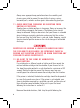
FIGURE 75 Slide rail both sides Slide rail both sides Striker block Disconnect cam Sear Cartridge guide Unlock block Extractor 1/4’’ from muzzle Slide rail both sides Barrel unlock surface Lubrication Points.
12.2 CLEANING AND LUBRICATION AFTER FIRING CAUTION: WEAR EYE PROTECTION AND PRACTICE SAFETY MEASURES APPROPRIATE FOR THE CHEMICALS BEING USED WHEN WORKING WITH SOLVENTS TO AVOID SERIOUS INJURY. MANY SOLVENTS ARE HIGHLY FLAMMABLE. 1. Completely unload the pistol as described in Section 6.3. 2. Disassemble the pistol as described in Section 11.1. 3. With a cleaning brush or a spray, apply solvent inside the barrel and allow the product to penetrate for a few minutes.
8. Clean all of the parts of the pistol and magazine that are accessible using a soft cloth or rag dampened with a lightweight gun oil or multipurpose lubricant and nylon brush, if needed, to remove the fouling and debris accumulated during firing. 9. Check the disassembled parts of the pistol for signs of wear and/or damage. In case of doubt about the condition of a part, consult an FN authorized individual. 10.
13. SCHEMATIC AND PARTS LIST 13.
402 03 3 404 403 108* 400 406 413** 405 408 407 414*** 401 409 410 412*** 411*** 301 111F 112 300F 305F 302F 214 303 304 59
FN 509 STANDARD MODEL PART LIST Number Description Number Description Unlock Block 206 Extractor 102 * Pin, Unlock Block Retaining 207-A* Pin, Extractor 103 Trigger Assembly 208 Spring, Extractor 104 Lever, Slide Stop 209 Striker 105 Spring, Slide Stop 210 Spring, Striker Return 106 Pin, Trigger 211 Striker Spring Stop 107 Lever, Take Down 212 Pin, Striker Spring Stop 108 * Pin, Fire Control 213 Spring, Striker 109 Release, Magazine 214 Guide, Striker Spring 110 Sprin
Number Description 400-B Fire Control Assembly, 509, MS 401 Housing, Left 402 Housing, Right 403 Sear 404 Carrier, Sear 405 Cam, Disconnect 406 Spring, Disconnect 407 Spring, Sear 408 Spring, Carrier 409 Pin, Carrier 410 Pin, Carrier Spring 411*** Spring, Detent 412*** Bearing, Ball 413** Clip, Retaining 414*** Overmold, Manual Safety 61
13.
FN 509 TACTICAL MODEL 203-A * Replacement recommended after removal 63
FN 509 SERIES MRD SLIDE ASSEMBLIES PARTS LIST Number Description Number Description 201 Slide, FN 509T, Gaurded 502 MRD Plate, RMR 202 Barrel, 4.
513 510 505 501 511 506 507 502 503 515 515 512 514 504 516 520 501 509 NOTE: MRD Plates identification markings. Example 501 is marked 1.
13.
300X-F 300F 300X-F 300F 300X-M 300X-F 300F-B 300M 300F 300X-M 300F-B 300M 300X-M 300C-B 300F-C 300C-A 300M-B 300F-B 300M 300C-B 300C-A 300F-C 300M-B 300X-C 300C-B 300C-A 300M-B 300F-C 67
FN 509 SERIES FRAME & MAGAZINE ASSEMBLY PARTS LIST Number 68 Description Number Description Full Size Frame Midsize Frame 111F-A Backstrap, Small, Black 111M-A Backstrap, Small, Black 111F-B Backstrap, Medium, Black 111M-B Backstrap, Medium, Black 111F-C Backstrap, Large, Black 111M-C Backstrap, Large, Black 300F 509 Magazine Assembly, 17 Rd, Black 300M 509M Magazine Assembly, 15 Rd, Black 300X-F 509 Magazine Assembly, 24 Rd, Black 300F-B 509M Magazine Assembly, 17 Rd, Black 300X-
Number Description Compact Frame 111C-A Backstrap, Small, Black 111C-B Backstrap, Medium, Black 111C-C Backstrap, Large, Black 300C-B 509C Magazine Assembly, 12 Rd Flat, Black 300C-A 509C Magazine Assembly, 12 Rd Pinky, Black 300M-B 509C Magazine Assembly, 15 Rd, Black 300F-C 509C Magazine Assembly, 17 Rd, Black 300X-C 509C Magazine Assembly, 24 Rd, Black 69
14. WARRANTY, SERVICE AND TECHNICAL QUESTIONS Returning your firearm for service When returning your firearm for service, be sure to follow the guidelines below: NOTICE: ALL FFL HOLDERS, IN ORDER TO AVOID UNNECESSARY RETURN SHIPPING DELAYS PLEASE SUBMIT AN FFL WHEN A FIREARM IS SENT IN FOR SERVICE. 1. Complete the online sign-up form and register to request service via FN’s website, www.fnamerica.com. 2. Be sure your gun is completely unloaded. 3.
IMPORTANT: Any addition to your FN firearm of aftermarket accessories (such as suppressors, triggers, muzzle devices, stocks, etc.) is considered a modification of your firearm from its original configuration, which may void your warranty. We are unable to adapt each firearm for every variable effect that might occur when you install a third-party manufacturer’s accessory on an FN firearm.
16. TECHNICAL SPECIFICATIONS FN 509 FN 509 TACTICAL FN 509 MIDSIZE 9mm Parabellum 9mm Parabellum 9mm Parabellum Length (in.) 7.4 7.9 7.4 Height (in.) 5.56 5.75 5.2 Width (in.) 1.35 1.35 1.35 Sight Radius (in.) 5.8 5.8 5.8 Barrel Length (in.) 4 4.5 4 Twist Rate (in.) 1:10 RH 1:10 RH 1:10 RH Weight w/ Empty Magazine (oz.) 26.9 27.9 26.5 17 24 & 17 15 Caliber Magazine Capacity Standard model Optional Trigger Pull (lbs.) 10 10 10 5.5 - 7.5 5.5 - 7.5 5.5 - 7.
FN 509 MIDSIZE MRD FN 509 COMPACT MRD 9mm Parabellum 9mm Parabellum Length (in.) 7.4 6.75 Height (in.) 5.3 5.2 / 4.8* Width (in.) 1.35 1.35 Sight Radius (in.) 5.8 5.6 Barrel Length (in.) 4 3.7 Twist Rate (in.) 1:10 RH 1:10 RH Weight w/ Empty Magazine (oz.) 26.5 26.5 15 12 & 15 Caliber Magazine Capacity Standard model Optional Trigger Pull (lbs.) 10 10 5.5 - 7.5 5.5 - 7.
NOTES: 74
NOTES: 75
WWW.FNAMERICA.