
Fireplace Manufacturers Inc Outdoor Fireplace User Manual


13
Fireplace Assembly Procedures
TOOLS NEEDED FOR INSTALLATION:
One4ft.level•
Roto-hammerwith½”drillbit•
DrillmotorwithmixerbladetomixMortar•
Twoempty5gallonbucketstomixMortar•
Onewheelbarrow• andshoveltomixconcrete
Groutbag•
Triangularmasonrytrowel•
Rubberhammer•
Spongeand2waterbucketstowipedownandmoisten•
partspriortoapplyingmortar
MATERIALS NEEDED FOR INSTALLATION:
Epoxyforsecuringrebarinfooting/foundation•
Three(3)-90lb.bagsofreadymixconcretewith¼”or•
smalleraggregate
MATERIALS INCLUDED:
8-⅜”Rebarx28”Long•
8-⅜”Rebarx12”Long•
1-50lb.bucketMortar•
20-SmallWoodShims•
Note-Wipeexcesswaterfromsurfacepriortoapplyinggrout.
Thiswillhelpgrouttoadheretosurfaceduringassembly.
Warning:Allsurfaceswheregroutisappliedmusthavewater
spongedonseveralminutespriortoassembly.Thiswillminimize
crackingofgroutjointandprovidemaximumstrength.
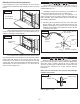
PlacetheGrandMeridianFireplacehearthbaseontopofyour
non-combustible oor. For concrete slabs, supporting oor
needstoberatedatASTM90.
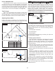
Drawanoutlineofthehearthareabasedonthedimensions1)
showninFigure 17.PositionHearthslabsandmarkrebar
centerlocations.Drill4inchesintoconcreteslabandsecure
the8piecesof12inchrebarwithepoxy.
Figure 17
LeftSideHearth2nd
RightSideHearth1st
Model W
MM39VF 43”
MM44VF 48”
MM49VF 53”
W
28”
Applymortar
betweenjoints
12inchrebar
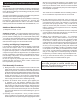
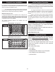
MixabatchofmortarandprepareRightSideHearthbottom2)
surfacetobebondedasshowninFigure 18.
Figure 18
1/2”AWAY
FROMEDGES
1/2”MORTAR
BEADTYPICAL
Hearthsectionshownprepared
forRightSideposition
APPLYMORTAR
BEADTOALL
MATINGSURFACES
AlignRightSideHearthtotheoutlinecreated.Theoverall3)
widthshouldallowforanapproximategapof1/8”between
slabsfortheadditionalmortartounitetheremainingslab.
Checkforsurfaceatness,levelifnecessary.
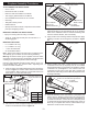
ApplymortartotheremainingHearthexceptthistimeapply4)
beadingonsurfacetobefacingoorasshowninFigure
19.
Figure 19
Hearthshownprepared
forLeftSideposition
Before installingside walls, conrm placementof outside5)
combustion air access (if required), this can be installed
eithersidedependingonwhichsideisaccessibletooutside
combustion air (all diagrams in this manual show the
combustion air inlet hole onthe right side). Prepare side
wallandrearwallmatingsurfaceswiththepreparedmortar
andbeginassembly.
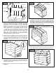
Figure 20
Side Wall shown prepared for Right Side Air
Access.ForLeftSidebeadoppositeside.
1/2”AWAY
FROMEDGES
Keeptheassemblyofthenextsectionsofthereboxside6)
wallsmovingup,keepingcomponentsmoist,mixingmortar
as youneed itand threading themortar appropriately as
youstackeachsection,oneontothenext.Constantlycheck
forsquarenessandlevelnesswhilebuildingeachcourseof
block.Asyoucompleteeachsection,makecertainthatyou
adherethemortarateachandeveryjoint.