
Fireplace Manufacturers Inc Outdoor Fireplace User Manual


9
Clearances
The Importance of Clearances
Warning to thestructural engineer and/orbuilding contractor:
It is your responsibility tobe certain that the Grand Meridian
Fireplacecan beproperly supportedby the combustibleoor
system on which the replace will rest. Be advised that this
engineering equation will be in addition to any live or dead
weightsthattheoorhastocarry.
Clearances to Combustibles
Nothing is more important than paying strict attention to
giving clearance between replace surfaces and surrounding
“combustibles”themostcommonofwhichare:
Drywall•
Woodooring•
Plywoodsub-ooring•
Framingmaterials•
Particleboard•
Millboard•
Plywoodpaneling•
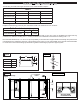
Required Clearances are:
Unitfront,sides,rear:..........................................0"
CombustibleFloor:.............................................0"
CombustibleSheathingaboveopeningtop:....... 8"(200mm)
Sheathingortrimtoopeningsides:....................8"(200mm)
Mantleaboveopening:.......................................12"(300mm)
Openingtosidewall:...........................................24"(500mm)
Insulationfromrebox:.......................................0"
The Grand Meridian Vent-Free replacemay be installed
at “zero clearance” to plywood sheathing and to uninsulated
woodframingmembersattheunitbottom,sides,rearandtop
whenusedforenclosinganylistedvent-freegas-redlogset
withmaximumheatinputratingsupto40,000Btu/hr.However,
whenaVent-Freereplaceistobeinstalledoncarpeting,wood
ooring,oranycombustiblematerialotherthantileorconcrete,
the Vent-Free replace shall then be installed on a metal or
woodplatformextendingthefullwidthanddepthoftheVent-
Freereplace.
Clearance to Combustible Trim:
Grand Meridian Vent-Free Fireplaces are designed to be
custom nished with facing trim and mantle to be an owner
option. However, all such trim material must meet standard
replacecoderequirements.
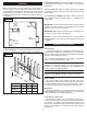
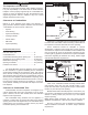
Non-combustible facing material must be applied to a
minimumofeightinches(8”)beyondthesidesofthenished
openingoftheVent-Freereplaceandnon-combustiblefacing
material mustcover aminimum oftwelve inches(12”) above
thenishedopeningoftheinstalledunit.
Figure 11
1-1/2”
8” MIN
NON-
COMBUSTIBLE
FACIA
Figure 12
1-1/2”
12” MIN
NON-COMBUSTIBLE
FACIA
Clearancetocombustibletrimarethosedistancesrequired
toensurethatcombustiblemantleandfacingmaterialwillnot
beexposedtoexcessiveheatwhiletheunitisoperating.
These clearances should be adequate to prevent
discolorationorwarpingoftrimfacingsduetoheat.However,
circumstancesuniquetoeachinstallationcreatevariablesthat
may be beyondthe scope of this manual.Therefore be sure
tofollow gaslogappliance manufacturer’s explicitinstallation
instructions regarding all minimum trim facing, mantle height
andsidewallclearancerequirements.
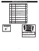
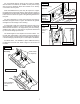
Figure 13
Parts of the combustiblemantle assembly located above
and projecting more than one and one-half inches (1-1/2”)
inches from the rebox opening shall bekept at least twelve
inches(12”)fromthetopoftheopening.
Mantleshelveswithhorizontalprojectionofteninches(10”)
fromthefaceofthereplacemustbeheldtoaminimumvertical
distance of twenty inches (20”) from the top of the nished
replaceopening.
Note: Mantle height clearances may vary among gas log
appliancemanufacturersorwiththeuseofreboxcanopies.
Be sure to follow the gas log appliance manufacturer’s
explicit installation instructions for mantle height clearance
requirements.