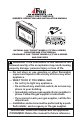
DIRECT-VENT Fireplace OWNER’S OPERATION AND INSTALLATION MANUAL PFS C ® US NATURAL GAS “TUDOR” MODELS (V)T32N-A SERIES, CGDV32NR and CTDV32NR-HA PROPANE/LP GAS “TUDOR” MODELS (V)T32P-A SERIES and CGDV32PR WARNING: If the information in this manual is not followed exactly, a fire or explosion may result causing property damage, personal injury or loss of life. — Do not store or use gasoline or other flammable vapors and liquids in the vicinity of this or any other appliance.
Table of Contents Safety................................................................... 2 Product Identification............................................ 4 Local Codes......................................................... 4 Product Features.................................................. 4 Pre-Installation Preparation.................................. 5 Location of Termination Cap................................. 7 Venting Installation...............................................
Safety Continued Carbon Monoxide Poisoning: Early signs of carbon monoxide poisoning resemble the flu, with headaches, dizziness or nausea. If you have these signs, the fireplace may not be working properly. Get fresh air at once! Have fireplace serviced. Some people are more affected by carbon monoxide than others. These include pregnant women, people with heart or lung disease or anemia, those under the influence of alcohol and those at high altitudes.
SAFETY Continued 8. Have venting system inspected annually by a qualified service person. If needed, have venting system cleaned or repaired. See Cleaning and Maintenance, page 30. 9. Do not use this fireplace to cook food or burn paper or other objects. 10. This appliance, when installed, must be electrically grounded in accordance with local codes or, in the absence of local codes, with the National Electrical Code, ANSI/NFPA 70. 11. Do not use fireplace if any part has been under water.
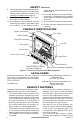
Product Features Continued sealed gas operating unit. It requires approximately 10-20 minutes of operating time before the flame pattern stabilizes. • Fireplaces with the suffix of -HA have been designed to operate at altitudes of 4000 feet and above. Pre-Installation Preparation Location and space requirements Determine the safest and most efficient location for your FMI PRODUCTS, LLC direct-vent fireplace. Make sure that rafters and wall studs are not in the way of the venting system.
Pre-Installation Preparation Continued NOTICE: This fireplace is intended for use as supplemental heat. Use this fireplace along with your primary heating system. Do not install this fireplace as your primary heat source. If you have a central heating system, you may run system’s circulating blower while using fireplace. This will help circulate the heat throughout the house. In the event of a power outage, you can use this fireplace as a heat source. Figure 4 shows typical framing of this fireplace.
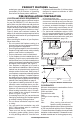
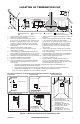
Location of Termination Cap N N D H V L E B C Fixed Closed F B Openable Fixed Closed V Openable V I V G B V B B J V G X G M A V K X V A V TERMINATION CAP X AIR SUPPLY INLET G GAS METER RESTRICTED AREA (TERMINATION PROHIBITED) I = clearance to service regulator vent outlet [*72" (182.9 cm) A = clearance above grade, veranda, porch, deck, or minimum] balcony [*12" (30.
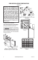
Venting Installation NOTICE: Read these instructions completely before attempting installation. These models are tested and approved for use with FMI PRODUCTS, LLC (direct-vent) pipe components and terminations. The venting system must terminate on the outside of the structure and can not be attached to a chimney or flue system serving a separate solid fuel or gas burning appliance. A direct-vent appliance must have its own venting system. DO NOT common vent this appliance.
Venting Installation Continued INSTALLATION PLANNING There are two basic types of direct-vent installation: • Horizontal Termination • Vertical Termination Horizontal Termination Installation IMPORTANT: Horizontal square terminations require only inner portion of wall firestop. Horizontal installations using round termination require exterior portion of wall firestop available only in vent kit HTK (see Figure 14, page 11). 1.
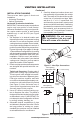
Venting Installation Continued 6. Noncombustible Exterior Wall: Position horizontal vent cap in center of the 8 1/2" round hole and attach to exterior wall with four screws (see Figure 10). Note: The four wood screws provided should be replaced with appropriate fasteners for stucco, brick, concrete or other types of sidings. Before attaching vent cap to exterior wall, run a bead of non-hardening mastic (pliable sealant) around outside edges to make a seal between it and outside wall.
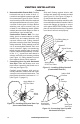
Venting Installation Continued Siding Standoff Minimum Pipe Overlap 1 1/4" Screws Wall Firestop Direct Vent Pipe Maintain 1" Minimum Air Space Around Outer Pipe When Penetrating a Wall GROUND FLOOR INSTALLATION Recommended Applications: • Installation using cabinet surrounds • Through the wall using round or square termination (up to 12") adjustable pipe) • NOT FOR CORNER INSTALLATION 45° Elbow Horizontal High Wind Square Termination High Wind Termination Adjustable Pipe 12" Wall Max.
Venting Installation Continued CORNER INSTALLATION Recommended Applications: • Corner ground floor installation • Ground floor installation where pipe vents horizontally through wall (over 12" horizontal pipe) • Basement installation where one foot clearance from ground to termination is possible Not to Exceed 90° Elbow Not to Exceed Square (H) Limits (H) Limits Termination Square As Required 90° Termination for (V), See Elbow Chart for Pipe Section Required Wall Firestop Wall Firestop 45° Elbow 12" Min.
Venting Installation Continued HORIZONTAL SYSTEM INSTALLATION USING TWO 90° ELBOWS The following configurations show the minimum vertical rise requirements for a horizontal system using two 90° elbows. Venting with Two 90° Elbows Horizontal (H1) + Vertical (V) Horizontal (H1) Horizontal (H2) 5' min. 6' min. 7' min. 8' min. 20' max. 2' max. 4' max. 6' max. 8' max. 8' max. 6' max. 12' max. 18' max. 20' max. 20' max.
Venting Installation Continued installation for vertical termination Note: Vertical restrictor must be installed in all vertical installations. 1. Determine route your vertical venting will take. If ceiling joists, roof rafters or other framing will obstruct venting system, consider an offset (see Figure 19) to avoid cutting load bearing members.
Venting Installation Venting with One 90° Elbow Vertical (V) Horizontal (H) 5' min. 2' max. 6' min. 4' max. 7' min. 6' max. 8' min. 8' max. 20' max. 8' max. 45° Elbow Continued 6. Continue to add pipe sections until height of vent cap meets the minimum building code requirements described in Figure 7 on page 7. Note: You must increase vent height for steep roof pitches. Nearby trees, adjoining rooflines, steep pitched roofs and other similar factors may cause poor draft or down-drafting in high winds.
Venting Installation Continued starter elbow (see Figure 25) and a round horizontal termination be used. 45° Starter Elbow Vertical Venting V = 40' max. Note: Install restrictor into inner collar of fireplace as shown. 45° Elbow Figure 24 - Vertical Venting Configuration With No Horizontal Run (Vertical Round High Wind Termination Shown) High Altitude Installation Your FMI PRODUCTS, LLC direct-vent fireplace has been tested and approved for elevations from 0-2000 feet (USA).
Venting Installation Continued Number VKC-58 Description Corner Vent Kit, Galvanized (Includes 45° Elbow, 7"-12" Adjustable Pipe, Wall Firestop, Horizontal Termination, 6" Pipe, 90° Elbow, 18 Screws) HHTK-58 High Wind Round Horizontal Termination Kit (Includes Round Termination, Wall Firestop, 45° Elbow) HHT-58 High Wind Round Termination Kit, Galvanized HTK-58 Horizontal Round Termination Kit (Includes Round Termination, Wall Firestop, 45° Elbow) HT-58 Horizontal Round Termination, Galvanized HTS-58 Horiz
Fireplace Installation Continued 4. Be certain that all wire terminals are securely attached to terminals on blower motor and that screw retaining green ground wire is tight. 5. Mount speed control box to switch bracket by placing plastic control shaft forward through opening in switch bracket (see Figure 27). 6. While supporting speed control, secure control shaft with lock nut by pushing and turning lock nut with pliers clockwise until it is tight against front panel. Place provided control knob on shaft.
Fireplace Installation Continued 3. Place blower against lower rear wall of firebox outer wrapper with exhaust port directed upward and thermodisc positioned up near fireplace bottom. Thermodisc must be oriented near fireplace bottom as shown in Figure 29, in order to sense temperature and properly operate. Blower will be held in position against back wall by magnets incorporated onto blower housing (see Figure 29). 4.
Fireplace Installation Continued Installing Gas Piping to Fireplace Location WARNING: A qualified service person must connect fireplace to gas supply. Follow all local codes. CAUTION: For propane/LP units, never connect fireplace directly to the propane/LP supply. This heater requires an external regulator (not supplied). Install the external regulator between the fireplace and propane/LP supply. WARNING: For natural gas, never connect heater to private (non-utility) gas wells.
Fireplace Installation Continued We recommend that you install a sediment trap/drip leg in supply line as shown in Figure 32. Locate sediment trap/drip leg where it is within reach for cleaning. Install in piping system between fuel supply and fireplace. Locate sediment trap/drip leg where trapped matter is not likely to freeze. A sediment trap traps moisture and contaminants. This keeps them from going into fireplace gas controls.
Fireplace Installation Continued Test Pressures Equal To or Less Than 1/2 PSIG (3.5 kPa) 1. Close equipment shutoff valve (see Figure 34). 2. Pressurize supply piping system by either opening propane/LP supply tank valve for propane/LP gas fireplace or opening main gas valve located on or near gas meter for natural gas fireplace or using compressed air. 3. Check all joints from propane/LP supply tank for propane/LP or gas meter for natural gas to equipment shutoff valve (see Figure 35 or Figure 36).
Fireplace Installation Battery Cover Remote Control Unit Continued Installing Optional Wireless hand-held REMOTE CONTROL HRC100 and HRC200 Series NOTICE: Use only alkaline batteries (not included). Installing Remote Receiver 1. Open bottom louver and locate switch bracket on the left. 2. Unscrew switch bracket. Lean bracket forward so you are able to access the back of remote receiver. 3. Locate battery clip mounted on back of receiver.
Fireplace Installation Continued Removing Glass Door If replacement of glass is necessary, the entire assembly, glass and frame, must be replaced. If glass is broken, wear gloves and tape remaining fragments onto frame. 1. Remove screen/rod assembly from firebox, push rod either left or right and then down and forward. Set assembly aside. 2. Lift up on latches to unlock. There are two on top of firebox and two below firebox that hold glass door in place (see Figure 42). 3.
Fireplace Installation Continued 7. Install right brick panel using the same method described in step 5 for left brick panel. 8. Replace deflector shield using screws removed in step 4. 9. Follow instructions below to install logs, lava rock and ember material. 10. Close glass door, lock latches on top and bottom of door and replace screen (see steps 5 and 6 of Removing Glass Door, page 24). 11. Close top and bottom louvers. 5.
Fireplace Installation Continued 6. Place log #6 (left log) onto two pins on left side of back and front log. See Figure 49. 7. Place lava rock along sides and front of firebox bottom in areas that are visible only. It is not necessary to use all of the lava rock provided. 8. Pull ember material apart into pieces no larger than a dime. Place these pieces loosely and sparingly directly onto exposed section of front burner and along space between burner and grate prongs (see Figure 50).
Operation Continued LIGHTING INSTRUCTIONS TO TURN OFF GAS TO APPLIANCE 1. STOP! Read the safety information on page 26. 2. Open lower louver panel. 3. Turn off all electric power to fireplace. 4. Push in gas control knob slightly and turn clockwise to OFF. 5. Wait five (5) minutes to clear out any gas. Then smell for gas, including near the floor. If you smell gas, STOP! Follow “B” in the safety information on page 26. If you don't smell gas, go to the next step. 6.
Operation Continued Blower Control Knob (Optional Accessory) ON HI O ON OFF REMOTE LO FF PIL Selector Switch in Remote Position N OT O OFF Variable Control Knob Gas Control Knob in ON Position Figure 52 - Setting Selector Switch, Gas Control Knob and Variable Control Knob for Remote Operation On/Off Series (Model HRC100 and HRC101) Hold control button on hand-held remote until burner turns on. Hold control button again until burner turns off (see Figure 53).
Operation Continued Auto Shutoff Feature 1. If the average room temperature reaches a range of 82° F (28° C) to 92° F (33° C), the hand-held remote control will perform a safety override and shut the fireplace off. This feature is not available in the MANU mode. 2. The receiver continuously receives signals from the hand-held remote to control the room temperature. If the hand-held remote is misplaced, obstructed or for any reason cannot transmit to the receiver, the receiver will shut off the fireplace.
Inspecting Burners Continued If you pilot assembly does not meet these requirements: • turn fireplace off (see To Turn Off Gas to Appliance, page 27) • see Troubleshooting, page 32 BURNER FLAME PATTERN Burner flames will be steady, not lifting or floating. Flame patterns will be different from unit to unit and will vary depending on installation type and weather conditions. If the vent configuration is installed incorrectly, flames will lift or "ghost". This can be dangerous.
Cleaning and Maintenance Continued CAUTION: Wear gloves and safety glasses while handling or removing broken glass. Do not remove if glass is hot. Keep children and pets away from glass. If glass has been broken, carefully remove glass door (see Removing/Replacing Glass Door, page 23). Vacuum all glass pieces with a shop vac. CAUTION: Do not vacuum if pieces are hot. Use only the tempered glass door replacement intended for this fireplace (see Replacement Parts, page 36 for detail on ordering).
Troubleshooting WARNING: Turn off heater and let cool before servicing. Only a qualified service person should service and repair heater. CAUTION: Never use a wire, needle or similar object to clean pilot. This can damage pilot unit. Note: All troubleshooting items are listed in order of operation. OBSERVED PROBLEM POSSIBLE CAUSE REMEDY When ignitor button is pressed, 1. Ignitor electrode not con- 1. Reconnect ignitor cable there is no spark at pilot nected to ignitor cable 2.
TROUBLESHOOTING Continued OBSERVED PROBLEM POSSIBLE CAUSE REMEDY Pilot lights but flame goes 1. Gas control knob not fully 1. Press in gas control knob out when control knob is pressed in fully released 2. G a s c o n t r o l k n o b n o t 2. After pilot lights, keep gas pressed in long enough control knob pressed in 30 seconds 3. Equipment shutoff valve not 3. Fully open equipment shutfully open off valve 4. Pilot flame not touching 4.
TROUBLESHOOTING Continued OBSERVED PROBLEM POSSIBLE CAUSE Heater produces a whistling noise when burner is lit 1. Turning gas control knob 1. Turn gas control knob to LO to HI position when burner position and let warm up for is cold a minute 2. Air in gas line 2. Operate burner until air is removed from line. Have gas line checked by local propane/LP or natural gas company 3. Dirty or partially clogged 3.
TROUBLESHOOTING Continued WARNING: If you smell gas • Shut off gas supply. • Do not try to light any appliance. • Do not touch any electrical switch; do not use any phone in your building. • Immediately call your gas supplier from a neighbor’s phone. Follow the gas supplier’s instructions. • If you cannot reach your gas supplier, call the fire department. OBSERVED PROBLEM POSSIBLE CAUSE REMEDY Fireplace produces unwanted odors 1. Gas leak. See Warning statement above 1.
Replacement Parts Note: Use only original replacement parts. This will protect your warranty coverage for parts replaced under warranty. Contact authorized dealers of this product. If they can’t supply original replacement part(s), call FMI PRODUCTS, LLC at 1-866-328-4537. When calling, have ready: • your name • your address • model and serial numbers of your heater • how heater was malfunctioning • purchase date Usually, we will ask you to return the part to the factory.
Accessories NOTICE: All accessories may not be available for all fireplace models. Purchase these accessories from your local dealer. If they can not supply these accessories call FMI PRODUCTS, LLC at 1-866-328-4537 for information. You can also write to the address listed on the back page of this manual. Refractory Brick Liner Kit BL32DS This brick liner adds a touch of style to your direct-vent fireplace. Complete installation instructions included in this manual.
Parts Models (V)T32N-A, (V)T32NB-A, (V)T32NR-A, (V)T32NRB-A, (V)T32P-A, (V)T32PB-A, (V)T32PR-A, (V)T32PRB-A, CGDV32NR, CGDV32PR and CTDV32NR-HA 22-3 6 22-4 22-5 22-6 22-1 7 22-2 8 1 4 11 9 14 21 12 13 20 19 18 10 17 3 5 15 2 16 38 www.fmiproducts.
PARTS This list contains replaceable parts used in your fireplace. When ordering parts, follow the instructions listed under Replacement Parts on page 36 of this manual. PART NUMBER KEY NO.
PARTS Burner assembly Models (V)T32N-A, (V)T32NB-A, (V)T32NR-A, (V) T32NRB-A, (V)T32P-A, (V)T32PB-A, (V)T32PR-A, (V)T32PRB-A, CGDV32NR, CGDV32PR and CTDV32NR-HA 17 19 16 15 1 2 13 8 3 7 18 9 14 11 6 12 4 5 10 40 www.fmiproducts.
PARTS Burner assembly Models (V)T32N-A, (V)T32NB-A, (V)T32NR-A, (V) T32NRB-A, (V)T32P-A, (V)T32PB-A, (V)T32PR-A, (V)T32PRB-A, CGDV32NR, CGDV32PR and CTDV32NR-HA This list contains replaceable parts used in your fireplace. When ordering parts, follow the instructions listed under Replacement Parts on page 36 of this manual. KEY NO. PART NO.
NOTES _____________________________________________________ _____________________________________________________ _____________________________________________________ _____________________________________________________ _____________________________________________________ _____________________________________________________ _____________________________________________________ _____________________________________________________ _____________________________________________________ ___________________
NOTES _____________________________________________________ _____________________________________________________ _____________________________________________________ _____________________________________________________ _____________________________________________________ _____________________________________________________ _____________________________________________________ _____________________________________________________ _____________________________________________________ ___________________
Warranty KEEP THIS WARRANTY Model (located on product or identification tag)______________________________ Serial No. (located on product or identification tag)___________________________ Date Purchased ___________________________ Keep receipt for warranty verification.