
User's Manual


12
3
1
2
1
2
Product description
31
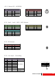
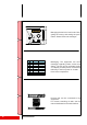
4.2.3 Stereo L/R − AES/EBU
4.2.4 Aux1 − Aux2 − MPX − MPX Monitor
4.2.5 RF Monitor
4.2.6 Line Input − Grounding
AC Line Input and Grounding − Cn no. 15
Pin. # Function AWG/sqmm Note
1 L1 11/4 max
2N1
G Gnd
3L2
230−400Vac
4N2
5L3
6N3
11/4 max
11/4 max
11/4 max
11/4 max
11/4 max
11/4 max
Stereo L/R (XLR) − Cn no. 16
Pin. # Function Type Note
1 Common Gnd //
2 Input L/R + Bal.
600Ω/10kΩ
3 Input L/R − Bal.
AES/EBU (XLR) − Cn no. 19
Pin. # Function Type Note
1 Common Gnd //
2 Input + Diff.
110Ω
3 Input − Diff.
MPX − Cn no. 17
Pin. # Function Type Note
1 Input Unbal.
600Ω/5kΩ
2 Common Gnd //
Aux1 + Aux2 − Cn no. 18, 15
Pin. # Function Type Note
1 Input Unbal.
10kΩ
2 Common Gnd //
MPX Monitor − Cn no. 20
Pin. # Function Type Note
1 Input Unbal.
10kΩ
2 Common Gnd //
RF Monitor − Cn no. 1
Pin. # Function Type Note
1 Output Unbal.
50Ω
2 Common Gnd //
1 2 3 4 5 6
G
hole for screws
up to M5