iRUGGY G8 Mobile Tablet User Manual Version 1.
G8 User Manual 2 Copyright Copyright 2017 All Rights Reserved Manual Version 1.0 The information contained in this document is subject to change without notice. We make no warranty of any kind with regard to this material, including, but not limited to, the implied warranties of merchantability and fitness for a particular purpose. We shall not be liable for errors contained herein or for incidental or consequential damages in connection with the furnishing, performance, or use of this material.
G8 User Manual 3 Pacemakers Pacemaker manufacturers recommended that a minimum of 15cm (6 inches) be maintained between a handheld wireless device and a pacemaker to avoid potential interference with the pacemaker. These recommendations are consistent with independent research and recommendations by Wireless Technology Research.
G8 User Manual 4 Caution! Any changes or modifications not expressly approved by the party responsible for compliance could void the user's authority to operate the equipment. CE Marking and European Economic Area The use of 2.4GHz RLAN's, for use through the EEA, have the following restrictions: Maximum radiated transmit power of 100 mW EIRP in the frequency range 2.400 ‐2.4835 GHz In France, outside usage is restricted to 2.4 ‐ 2.454 GHz. Italy requires a user license for outside usage.
G8 User Manual 5 Version Date Changes 1.
Table of Contents 1 2 Unpacking the unit ................................................................................................................................ 8 1.1 Standard items .............................................................................................................................. 8 1.2 Accessories .................................................................................................................................... 8 Hardware Overview .................
G8 User Manual 7 6.2 Connecting to Network and Peripherals ..................................................................................... 22 6.3 Placing the Tablet in the Dock .................................................................................................... 23 6.4 Installing the Customer Display .................................................................................................. 24 6.5 Installing a third‐party payment device ..................................
G8 User Manual 8 1 Unpacking the unit The following items may be shipped with each unit. 1.1 Standard items Tablet AC Adapter iRUGGY G8 Quick Start Guide Standard Hand Strap Quick Start Guide 1.
G8 User Manual 9 HF RFID ADD‐f(x) Module Smart Card Reader / MSR ADD‐f(x) Module mPOS Integration Bracket Mounting Plate Ingenico iCMP mPOS Integration Bracket POS Docking Station POS Dock mPOS Bracket Mount POS Dock Customer Display VESA Charging Dock Confidential and Proprietary Information
G8 User Manual 10 2 Hardware Overview 2.
G8 User Manual 11 2.
G8 User Manual 12 2.3 Specifications Touch Display Processor Operating systems Memory / Storage¹ Camera Expansion I/O ports Audio Communications Power Supply Environmental Dimensions (W x H x D) Weight (with Battery)⁴ ADD‐f(x) modules⁵ Optional accessories⁵ 8.0” (800 x 1280 resolution) projected capacitive multi‐touch display User‐selectable touch mode for Hand, Glove, Stylus or Rain Programmable capacitive function key on front‐bezel Intel® Quad‐Core CPU 2.
G8 User Manual 13 3 Product Labelling Safety certification and other compliance labels may be found on the inside of the battery compartment, along with product serial number and Windows license sticker. See section on Removing the Battery for instructions on removing the battery module to view this information. All tablets are labelled with a unique serial number. This number is important in tracking units through production and shipment and may be required for servicing the product under the warranty.
G8 User Manual 14 4 Basic Operation 4.1 Power On/Off Button Power On/Off button in4Touch™ touch mode control button 4.1.1 Turning on the Unit Press and hold the power button 2 seconds on to turn on the system. You will feel a vibration the moment the system powers on. NOTE: The tablet must be docked, plugged into AC or battery charged before turning on the unit for the first time. 4.1.2 Turning off the Unit The unit should be shut down normally via the operating system.
G8 User Manual 15 4.3 Adjusting Screen Brightness Windows display settings allow screen brightness to be set manually or adjusted automatically for power savings or for comfort under different lighting conditions. There are 4 manual settings: 100%, 75%, 50% and 25%. Factory default setting for the display is fixed at 100% brightness. An ambient light sensor located on the front of the display may be used to sense and reduce the brightness level for comfort in low light environments.
G8 User Manual 16 4.6.2 Battery Level Indicator on Tablet A battery level indicator LED on the front of the tablet signals charge status: GREEN ORANGE RED/Flashing RED Battery charge level is 90% or higher (Tablet is plugged in or placed in dock) Battery is charging (Tablet is plugged in or placed in dock) Battery level below 15% Battery level below 10% 4.7 Replacing the Battery 4.7.
G8 User Manual 17 Slide latch right to unlock Next slide the latch holding the main battery module in place and lift out the battery at an angle as shown above. 4.7.2 Installing the Battery Angle the battery module so that the left side with exposed connector pins is inserted first into the battery compartment. The press into place and slide the latch upward to lock the battery module into position. 5 Installation and Setup 5.
G8 User Manual 18 5.2 Attaching the Hand Strap Use of the standard hand strap shipped with the tablet is optional. Depending on the situation, the user may attach the hand strap between anchor points across the top or either side of the tablet. To attach the strap to the tablet, thread both ends of the strap into an anchor point, fold back and tighten in the plastic buckle. Any excess can be tucked into the sleeve handle at the center of the strap. 5.
G8 User Manual 19 3G SIM slot Orient either card so that the gold contact edge faces down towards the front of the tablet. Slide the card in until it clicks in place. To remove the card, press the outer edge to click and release the card.
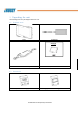
G8 User Manual 20 5.4 Installing ADD‐f(x)™ Modules Optional ADD‐f(x) modules are available to expand tablet functionality. To install any module, first power down the system. Locate the three universal expansion bays on the top, back side of the tablet. Depending on the number and size of the modules selected, one or all three bays may be used to install 1, 2 or up to 3 ADD‐f(x) modules. Remove the two screws and lift off the plastic cover covering each bay. This cover may be saved or discarded.
G8 User Manual 21 5.5 Attaching an mPOS Integration Bracket Custom brackets are available for on‐tablet integration of third‐party mobile point‐of‐sale (mPOS) payment devices, such as the Ingenico iCMP mobile payment device. To attach the bracket, place the tablet face down. Position the metal universal mounting plate over the battery module as shown and attach with the four screws provided (you may need to first remove and discard cosmetic rubber covers placed over the screw holes).
G8 User Manual 22 6 Using the G8 POS Docking Station An optional countertop mount is available to allow the G8 tablet to be operated at different angles while docked for charging, LAN communication and connection with peripherals. The docking station also supports optional mounting of a customer display or third‐party payment terminal. 6.
G8 User Manual 23 6.3 Placing the Tablet in the Dock The tablet may be placed on the dock powered on or off. When positioning the tablet on the dock, take care to locate the extension on the back center of the tablet and make sure this slides over the tab on the mount. Open position Locked position There is a latching mechanism to secure the tablet in the dock, accessed on the back of the mount. Before placing the tablet in the dock, check to make sure the latch is in the open position.
G8 User Manual 24 6.4 Installing the Customer Display An optional 2 line x 20 graphic LCD customer display may be mounted on the back of the docking station. Contact your iRuggy Systems or authorized sales representative for a copy of the separate user guide and OPOS driver for the customer display option. To install the customer display, remove the single screw securing a cover over the rear mount area and discard.
G8 User Manual 25 6.5 Installing a third‐party payment device An optional mounting post is available to attach a third‐party payment device on the back of the docking station. The post is compatible with device‐specific mPOS brackets supplied by iRuggy Systems. To install the device mount, remove the screw and discard the blanking cover over the rear mount access. Attach the post to the base with the four screws provided before attaching the iRuggy Systems mPOS bracket.
G8 User Manual 26 7 Using the G8 VESA Charging Dock An optional fixed position mount is available to operate the tablet while charging. This mount features a 75 x 75 mm VESA hole pattern for attaching the mount to any VESA compatible wall or post bracket. The AC adapter shipped with the tablet may then be plugged directly into the DC‐in connector on the charging dock. The tablet may be placed on the dock powered on or off.
G8 User Manual 27 8 Using the G8 Vehicle Mount An optional vehicle mount is available to secure the tablet onto a vehicle specific bracket. This mount features a 75 x 75 mm VESA hole pattern. A cigarette lighter adapter shipped with the vehicle mount is plugged into the mount and standard cigarette lighter outlet to keep the tablet charged. The vehicle mount also features a 5V PC USB port to connect USB peripherals. The tablet may be placed on the dock powered on or off.
G8 User Manual 28 9 Software Configuration All Windows or Android software and device drivers required to operate the tablet with any standard or optional features or accessories are pre‐installed at the factory. There is no need to download and install additional driver software, even for ADD‐f(x) accessories shipped separately. Contact your iRuggy Systems authorized distributor or reseller for technical information required for software integration or specific device configuration.
G8 User Manual 29 Appendix A: Supported Bar Code Symbologies Below bar codes types are supported by the optional 1D/2D scanner ADD‐f(x) module: Aztec Code Codabar Codablock F Code 11 Code 32(PARAF) Code 128 Code 2 of 5 Code 39 Code 93 Data Matrix EAN/JAN‐13 EAN/JAN 8 EAN‐UCC Composite Codes EAN‐UCC Emulation IATA Code 2 of 5 Interleaved 2 of 5 Matrix 2 of 5 MaxiCode MicroPDF417 MSI, PDF417 QR Code GS1 DataBar TCIF Linked Code 39 UPC‐A UPC E RSS Expanded RSS Limited RSS‐14 Chinese Sensible (Han Xin) code C