
User Manual

7
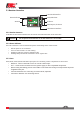
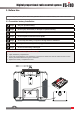
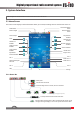
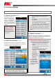
2.3 Receiver Overview
Power/Bind Port
To Servos
PPM Output /To Servos
Antenna
Status Indicator
i-BUS Sensor Interface
i-BUS Serial Interface
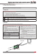
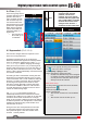
2.3.1 Receiver Antenna
Attention • Do not pull or tie the antenna or use the antenna as a servo cable.
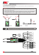
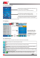
2.3.3 Ports
Power, Bind, Channel,Serial and PPM output ports for connecting various components to the receiver.
• PPM/CH1:CanbeconnectedtoservoorusedasaPPMoutput.
• CH2 ~CH10:Canbeconnectedtoservos,powersupplyorothercompatiblecomponents.
• B/VCC: During the binding process a bind cable is connected here. During normal opertaion the power
is applied to this port.
• i-Bus Serial Interface: For connecting an i-BUS module, expansion.
• i-Bus Sensor Interface: For connecting sensors.
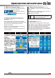
2.3.2 Status Indicator
The status indicator is used to indicate the power and working status of the receiver.
• Off: the power is not connected.
• Lit in red: the receiver is on and working.
• Flashing quickly: the receiver is binding mode.
• Flashing slowly: the bound transmitter is off or signal is lost.
FS-iA10B uses dual 26mm antenna and can receive and send information at the same time.