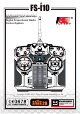
FS-l10 INSTRUCTION MANUAL Digital Proportional Radio Control System Copyright ©2013-2017 Flysky RC model technology co.
Thank you for purchasing our product, an ideal radio system for beginners or experienced users alike. Read this manual carefully before operation in order to ensure your safety, and the safety of others or the safe operation of your system. If you encounter any problem during use, refer to this manual first. If the problem persists, contact your local dealer or visit our service and support website for help: http://www.flysky-cn.
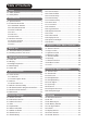
Table of Contents 1. Safety .....................................................1 1.1 Safety Symbols ............................................................1 1.2 Safety Guide ................................................................1 2. Introduction ..........................................3 2.1 System Features ..........................................................3 2.2 Transmitter Overview ...................................................4 2.2.1 Transmitter Antenna ....................
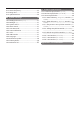
9.10 i-BUS Setup .............................................................35 9.11 Servos Frequency ..................................................35 9.12 Range Test ...............................................................36 9.13 Update Receiver ....................................................36 10. System Settings ................................37 10.1 Blacklight Timeout: (Time) .................................37 10.2 Backlight: (%) ......................................................
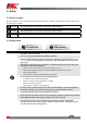
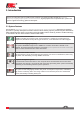
1. Safety 1.1 Safety Symbols Pay close attention to the following symbols and their meanings. Failure to follow these warnings could cause damage, injury or death. Attention • Not following these instructions may lead to minor injuries. Warning • Not following these instructions may lead to major injuries. Danger • Not following these instructions may lead to serious injuries or death. 1.2 Safety Guide Prohibited Mandatory • Do not fly at night or in bad weather like rain or thunderstorm.
Digital proportional radio control system 2 FS-l10 • Misuse of this product can lead to serious injuries or death. To ensure the safety of you and your equipment, read this manual and follow the instructions. • Make sure the product is properly installed in your model. Failure to do so may result in serious injury. • Make sure to disconnect the receiver battery before turning off the transmitter. Failure to do so may lead to unintended operation and cause an accident.
2. Introduction The FS-i10 transmitter and FS-iA10B receiver constitute a 10 channel 2.4GHz AFHDS 2A(Automatic Frequency Hopping Digital System Second Generation) digital proportional computerized R/C system. This system supports fixed-wing, glider and helicopter. 2.1 System Features The AFHDS 2A (Automatic Frequency Hopping Digital System Second Generation) developed and patented by FLYSKY is specially developed for all radio control models.
Digital proportional radio control system FS-l10 2.
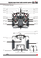
2.2.1 Transmitter Antenna Note Note Note • To ensure high signal quality, the antenna should be perpendicular to the models fuselage. When adjusting the angle of the antenna, make sure that the antenna does not point directly towards the front or back of the model. • Never grip the transmitter antenna during operation. It significantly degrades signal quality and strength and may cause loss of control. • Do not bend the antenna wire beyond 90 degrees.
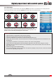
Digital proportional radio control system FS-l10 2.2.6 Stick Mode The system supports 4 stick modes, the default is [Mode 2]. The blue icon indicates the currently selected mode. Enter the main menu, touch the [System] icon and select your prefered mode. Mode Elevator Mode Throttle Throttle Aileron Rudder Aileron Rudder Mode Elevator Elevator Mode Throttle Throttle Elevator Rudder Aileron Rudder Aileron Changing from modes 2/4 to 1/3 will change the throttle position.
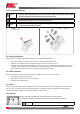
2.3 Receiver Overview i-BUS Serial Interface Status Indicator Antenna Power/Bind Port To Servos PPM Output /To Servos i-BUS Sensor Interface 2.3.1 Receiver Antenna FS-iA10B uses dual 26mm antenna and can receive and send information at the same time. Attention • Do not pull or tie the antenna or use the antenna as a servo cable. 2.3.2 Status Indicator The status indicator is used to indicate the power and working status of the receiver. • • • • Off: the power is not connected.
Digital proportional radio control system FS-l10 3. Before Use Before using the product please follow the guidelines below to install the battery and connect the device. 3.1 Transmitter battery Installation Danger • Only use specified battery. Danger • Do not open, disassemble, or attempt to repair the battery. Danger • Do not crush/puncture the battery, or short the external contacts. Danger • Do not expose to excessive heat or liquids.
3.2 Installing Receiver and Servos Make sure that you find an appropriate location to mouth the receiver in order to, ensure performance, stability and prevent outside interference. Installation: 1. 2. 3. Make sure the receiver is mounted away from motors, electonic speed controllers or any device that emmits excessive electrical noise. Keep the receivers antenna away from conductive materials such as carbon or metal.
Digital proportional radio control system FS-l10 4. Operation Instructions Follow these guidlines to ensure proper use of your system 4.1 Power On Follow these steps to power on the system: 1. Check the system and make sure that: • The battery is fully charged and installed properly. 。 • The receiver is off and correctly installed. 2. Hold both power buttons on either side of the LCD until it lights up 3. Connect the receiver power supply to the B/VCC port on the receiver.
4.3 Preflight Inspection Before you begin, perform the following steps to ensure the system performs as expected: 1. Check the entire system to ensure that all components function as expected. 2. Perform a distance signal test as outlined in 【9.13 Range Test】. Danger • If there are any problems during testing, no not operate the model. Danger • Make sure that the model does not go outside safe operating range. Attention • Be aware of sources of interference that can affect signal quality. 4.
Digital proportional radio control system FS-l10 5. System Interface This chapter is an introduction to the menu and menu functions. 5.1 Home Screen The home screen displays useful information about your model, including sensors and function status etc.
5.1.2 Interface Quick Guide Touch this area to quickly enter the sensor selction menu; Up to 4 sensors can be displayed. To select a sensor, refer to 【9.8 Choose Sensors 】. Touch this area to quickly enter the timer menu; To set up a timer refer to 【6.23 Display Servos】. Touch this area to quickly enter the Aircraft Structure menu; To change the aircraft structure refere to 【6.25 Models】. 5.
Digital proportional radio control system FS-l10 5.3 Built-in Contextual Help(Pic.1) 5.5 Reset Function Interface(Pic.3) The help icon is both in the title and bottom bars. Touch the left side of the bottom bar When [ICON] is touched the system will display a prompt: [Yes]: Select yes to return the current function or menu to its factory default setting. [NO]: Select no to cancel. or the right side of the title bar top to gain access to the contextual help menu. Note • 5.
6. Function Settings This section contains the default menu function settings. 6.1 Reverse Function (Pic.5) The Reverse function is used to correct a servo or motor’s direction in relation to the systems controls. For example, if a servo is mounted upside down in order to fit inside a model. • Pic.5 To reverse a channel: This menu contains 10 check boxes, one for each channel, when a channel is reversed the corresponding box will be checked.
Digital proportional radio control system 6.4 Trims (Pic.8) There are 4 groups of trim switches affecting surface position. Each time a trim is toggled, the trim will move one step. You can hold the trim in the desired direction to make quicker trim adjustments. When the trim position reaches the middle, the transmitter beeps in a higher tone. • This function can be set with up to 5 conditions. • Pic.8 Note FS-l10 The system gives a real time readout of the channels position, not the servo position.
6.6 Aileron to Rudder (Pic.10) The aileron to rudder automatically creates a coordinated turn for the aircraft with aileron and rudder. The pre-programmed mix is 10% by default, meaning that if your aileron has moves to 100% of its range of movement the rudder will move 10%. If the aircraft does not have ailerons or a rudder, these function icon will not be displayed. When this function is activated, a tick will be shown on the bottom left side of the screen, if not press the bottom left icon. Pic.
Digital proportional radio control system Editing Curves FS-l10 Pic.12 To edit a curve touch one of the points listed at the bottom of the screen then use the wheel to change its value. • This function can be set with up to 5 conditions. Setup: 1. 2. 3. Activate the function by touching the function on/off icon located at the bottom left of the screen.
6.11 Aux Channels(Pic.15) 6.13 Function Delay(Pic.17) The model function allows users to set auxiliary channels. Every channel that is not assigned during the model setup will be set as an AUX channel. AUX channels can be used to control various extra features on an aircraft including landing gear, brakes, lights... Function delay is used to slow down the response speed of basic function output. It can be adjusted from 0 to 10 seconds.
Digital proportional radio control system 5. Setup: 1. 2. Select desired channel. Move the wheel to modify the delay time. • This function can be used to emulate movements of real aircraft. For example if a scale model of a real airplane is being used, it is possible to use this function to imitate the reaction time of the real plane. FS-l10 Select low side and high side to set the limits of movement for the slave channel.
2. 3. 4. Select the master, this channel/input will control the slaves output. It is also possible to select stick/knob, basic functions or a channel output. Select a slave, slaves may only be output channels. If desired apply a curve to the mix, to do this select the curve option, select a number/point below the graph and use the wheel to change the value. • This function can be set with up to 5 conditions. 6.19 Logic Switches(Pic.
Digital proportional radio control system FS-l10 6.20 Airplane Structure (Pic.24) Airplane structure enables you to set the control surfaces on your model. To add or remove available surfaces first select [Modify] at the bottom right side of the screen, select each control surface available on your model so that a tick is displayed in a box next to the name.
These functions are also known as basic functions, as referred to in the [Trainer Mode], [Curve Mixes], [Function Delay] and [Linear mixes] sections of this user manual. Some functions can apply the function of one control surface to another, for example, the aileron function can apply aileron control to flaps and elevators. This can be used to enhance the effect of a control surface in order to make the model more responsive and agile.
Digital proportional radio control system FS-l10 6.22 Trainer Mode (Pic.26) This function allows you to connect 2 transmitters together using a dedicated cable connected to the back of the FS-i10. The FS-i10 that enables the trainer function will become the master, and will be able to override the other FS-i10. Usually this function is used by instructors to teach students how to fly, they can give the student full control but can quickly step in if anything goes wrong.
of the signal. This is measured from -120dBm to -60dBm. The higher up the graph the signal appears the stronger it is, and has a bigger chance of causing interference. Along the bottom of the graph is a solid block of red, this in this case is just background noise. Background noise usually isn’t a problem and a level of background noise can be expected everywhere. Along the graph at different frequencies red spikes can be seen.
Digital proportional radio control system FS-l10 [Copy model]: Copies the settings of a model to overwrite another model. To copy a model: 1. Select [Copy model]. 2. Select a copy source the setting of which will be copied. 3. Select a target model that you wish to overwrite. 4. Select [Yes] in the confirmation box and the target model will be overwritten by the copied model. [Import model]: Imports models from an SD card. To import select the desired model from the list.
7. Airplane / Glider Menu Functions This chapter introduces airplane / glider features, in addition to features already described in the chapter 6. 7.1 Aileron Function(Pic.30) The aileron function enables flaps to be used as ailerons. The function sets a ratio between aileron and flap movement which can be customized for the users’needs. For example if flap one is set to 10% in the down column, when the aileron is at 100% movement the flap will have moved 1/10th of that distance. Pic.30 1.
Digital proportional radio control system FS-l10 7.4 Elevator to Flap(Pic.33) 7.6 Butterfly(Pic.35) The elevator to flap function creates a mix between the elevator and flaps. For example if flaps are 10% on the high side, when the elevator is at 100% movement the flap will have moved 1/10th of that distance. The Butterfly function is used with gliders and is a wing function is used when landing. Usually when the butterfly function is activated the flaps drop down and the ailerons move upwards.
7.8 Rudder Function(Pic.37) 7.9 V-tail(Pic.38) The rudder function is used for aircraft that have 2 rudders. Each rudder can set its own ratio to the sticks movement. For example if rudder 1 is set to 10% on the up side, when the stick Pic.37 is at 100% movement in that direction, the rudder will only move 10% of its full range of motion. The V-tail function is used for planes that have no elevators and has a V-tail rudder configuration.
Digital proportional radio control system FS-l10 8.Helicopter Menu Functions This chapter introduces helicopter features, in addition to features already described in the chapter 6. 8.1 Throttle Hold(Pic.39) Throttle hold locks the throttle to a preset value, once the throttle hold function has been activated the stick will no long be able to change the throttle. The throttle hold function must be assigned to a switch or logic switch to function.
8.4 Swashplate Mix(Pic.42) 8.6 Hover Adjust(Pic.44) This function is used to edit the pre-programmed mix control of the helicopter’s aileron, elevator and pitch. Adjust the motion range Pic.42 of these three functions to achieve the desired maneuverability. Refer to your models manual to ensure best results. If your model is moving up or down, or moving in a direction when hovering, use this function to correct this. If the model is gaining or losing altitude, adjust the throttle setting.
Digital proportional radio control system 8.8 Governor(Pic.46) FS-l10 Pic.46 The function of a governor is to keep the head speed constant, independent of varying load on the motor. A constant RPM is a good thing for 3D flight since the cyclic and rudder functions (and gyro gain) will remain constant throughout the entire flight envelope.
9. RX Setup This chapter introduces receiver features. 9.1 Bind with a Receiver This menu is for binding the transmitter and receiver. For instructions on binding, please refer to [4.2 Binding]. 9.2 RF Std This menu allows you to change the communication protocol for the transmitter.
Digital proportional radio control system FS-l10 9.6 Failsafe (Pic.50) This function is used to protect the models and users, if the receiver loses signal and therefore is no longer controllable. All channels are listed in the failsafe menu. [Off] means that in case of a loss of signal, the corresponding servo will keep its last received position. If it displays a percentage, the servo will instead move to the selected position. Setup: Pic.50 1. Select a channel. 2.
9.8 Choose Sensors The main screen can display the value of up to 4 sensors. This function is used to select which sensors to display. To choose a sensor: 1. Select a slot, 1, 2, 3 or 4. Any sensors that are connected will automatically populate this list. 2. Select the desired sensor and exit the function. To set the alarm limits for a sensor: 1. Activate the function. Make sure that the icon is displayed in the bottom left corner. If not, press the icon to enable. 2.
Digital proportional radio control system FS-l10 9.12 Range Test This function temporarily reduces the transmitter’s power to allow for a manageable range test. Instead of having to walk several hundred meters away from the receiver, it is possible to test the range by pressing SW2 and walking at most 30 meters away from your model. 9.13 Update Receiver This function is used to update the firmware of the receiver. Setup: After selecting [Update receiver], the FS-i10 will ask for a conformation.
10. System Settings The menu system is used to set transmitter functions such as screen and audio settings. 10.1 Blacklight Timeout: (Time) The blacklight timeout function controls how long the system will wait before turning off screens backlight. • Backlight time can affect the battery life of your system, the longer the time, the shorter the battery will last.To change the backlight time enter the function and select the desired time from the list. 10.
Digital proportional radio control system FS-l10 10.10 Firmware Update The internal software of the transmitter can be updated using the USB interface connected via a PC computer. Once this function is activated, all functions of the transmitter stop. To avoid any loss of control of the vehicle, turn its receiver off before entering this mode. A confirmation is requested. When the firmware is updating, never disconnect the USB cable or remove the battery or the transmitter will become unusable.
11. Product Specification This section contains the FS-i10, FS-iA10B and sensor specifications. 11.1 Transmitter Specification (FS-i10) Channels 10 Model type Fixed-Wing/Glider/Helicopter RF range 2.408 ~ 2.475 GHz Bandwidth 500 KHz Band 135 RF power Less then 20 dBm 2.4G system AFHDS 2A Code type GFSK Stick Resolution 4096 Low voltage alarm Yes (lower than 3.75V) DSC port Yes (Micro-USB) Power input 3.
Digital proportional radio control system 11.3 Sensor Specification 11.3.1 RPM Telemetry (Magnetic) Module(FS-CPD01) Model type Car/Boat/Plane Speed range 0 to 60000 rpm Power input 4.0 to 6.5 V DC Weight 6.6g Dimension (Length x Width x Height) 31*15*8.5 mm Color Black 11.3.2 RPM Telemetry (Optical) Module(FS-CPD02) Model type Car/Boat/Plane Speed range 0 to 60000 rpm Power input 4.0 to 6.5 V DC Weight 6.8g Dimension (Length x Width x Height) 31*15*8.5 mm Color Black 11.3.
11.3.6 i-Bus Receiver(FS-CEV01) Model type Car/Boat/Plane Power input 4.0 to 6.5 V DC Weight 7g Dimension (Length x Width x Height) 32*15.6*7.5mm Color Black i-Bus port Yes Channels 1 11.3.7 i-Bus Receiver(FS-CEV02) Model type Car/Boat/Plane Power input 4.0 to 6.5 V DC Weight 7.6 g Dimension (Length x Width x Height) 32*16*10 mm Color Black i-Bus port Yes Channels 2 11.3.8 i-Bus Receiver(FS-CEV04) Model type Car/Boat/Plane Power input 4.0 to 6.5 V DC Weight 6.
Digital proportional radio control system FS-l10 Appendix 1 FCC Statement This equipment has been tested and found to comply with the limits for a Class B digital device pursuant to part 15 of theFCC rules. These limits are designed to provide reasonable protection against harmful interference in a residential installation.
http://www.flysky-cn.com Copyright ©2013-2017 Flysky RC model technology co.