Pac a Mow Original Instructions TIO A M R N NFO I T TA N se R nce O I M P before u re refere tu Read in for fu ta & re For all customer enquiries or for replacement parts, contact:- 01325 300303 www.flymo.com customer.services@husqvarna.co.
Carton Contents cable hook x 2 upper handle screw x 2 round headed bolt x 2 barrel nut x 4 electric cable with moulded on plug cam lock x 4 washer x4 lower handle cable clip grassbox square headed bolt x 2 pivot block x 2 spring x 2 spanner instruction manual IMPORTANT ! Please check the contents of the carton are correct BEFORE assembling your new Flymo product. IF ANY PARTS ARE MISSING CONTACT:Husqvarna UK Ltd.
current of not more than 30mA. Even with a R.C.D. installed 100% safety cannot be guaranteed and safe working practice must be followed at all times. Check your R.C.D. every time you use it. 2. Before use, examine cable for damage, replace it if there are signs of damage or ageing. 3. Do not use the lawnmower if the electric cables are damaged or worn 4. Immediately disconnect from the mains electricity supply if the cable is cut, or the insulation is damaged.
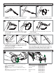
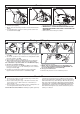
Assembly of Upper Handles to Lower Handles D1 D2 D3 x3 1. Insert the Barrel Nut into the Cam Lock as illustrated in fig D1. 2. Attach the Upper Handle to the Lower Handle with D4 D5 4. Fold down the Cam Lock towards the Handle as illustrated in fig D4, and continue to turn clockwise (D5) until tightened. E the Round Headed Bolt, Washer and Cam Lock as illustrated in fig D2 3. Turn the Cam Lock 3 times clockwise, as illustrated in fig D3. F 1 D6 5.
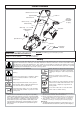
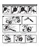
Assembly of Lower Handles to Lawnmower A1 A2 A3 1. Insert the Square Headed Bolt into the lawnmower as illustrated in fig A1. Then push the Bolt down until it is locked into position as illustrated in fig A2. 2. Place the Spring over the Bolt (A3) 3. Insert the Pivot Block on to the Bolt (A4) B C2 A4 C1 C3 pivot block lower handle x3 washer cam lock 4. Place the Lower Handle over the deck as illustrated in fig B. 5. Insert the Barrel Nut into the Cam Lock as illustrated in fig C1. C4 C5 7.
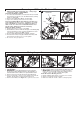
Grassbox L2 L1 L3 safety flap location points Fitting Grassbox to Lawnmower. 1. Lift Safety Flap.(L1) 2. Make sure the discharge chute is clean and free from debris. 3. Locate Grassbox onto the location points at the rear of the lawnmower (L2) 4. Locate Safety Flap onto the top of the Grassbox. (L3) Ensure the Grassbox is securely located. • IMPORTANT ! AFTER FITTING ENSURE NO GAP REMAINS BETWEEN THE SAFETY FLAP AND THE GRASSBOX. • Removal is the reverse procedure.
Removing and Fitting the Blade and Fan • Always handle the blade with care - sharp edges could cause injury. USE GLOVES. Removing the Blade and Fan 1. To remove the Blade Bolt, hold the Fan firmly and with the Spanner provided loosen the Blade Bolt by turning it anti-clockwise (S). 2. Remove the Blade Bolt, Blade, and Fan.(S) 3. Inspect for damage and clean as necessary. Renew your Metal Blade after 50 hours mowing or 2 years whichever is the sooner - regardless of condition.
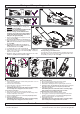
Storing and Transporting your Lawnmower V1 V3 V2 W Storing your Lawnmower • Warning:- This product is heavy, use extra care when lifting. • Warning:- Be careful when folding handles to prevent entrapment of fingers. • Before storage, ensure that the front height of cut is at its lowest (V1). Failure to ensure this will prevent the product from fitting into the grassbox (V2). 1. Remove the Grassbox and place in front of the product (V3). 2. Push the product halfway into the Grassbox, 3.
Environmental Information Husqvarna UK Ltd. products are manufactured under an Environmental Management System (ISO 14001) using, where practical, components manufactured in the most environmentally responsible manner, according to company procedures, and with the potential for recycling at the end of the productsʼ life. • Packaging is recyclable and plastic components have been labelled (where practical) for categorised recycling.