
Cut Sheet
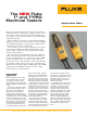

2 Fluke Corporation The NEW Fluke T+ and T+PRO Electrical Testers
Nice-to-haves
When working in dimly-lit loca-
tions, use the LED flashlight built
in to the tester to illuminate the
connections and guide your mea-
surement. The light stays on for
five seconds or as long as the
flashlight button is pressed. With
one probe locked into the built-
in probe holder, the tester’s light
will illuminate the area where
the probe is pointing.
The Fluke T+ and T+PRO come
with special, extra-heavy-duty
test leads that hold up lon-
ger against the wear and tear
of normal use than standard
leads. Both test leads also have
removable probe tips for easy
tip replacement and to allow
alternate probe tip styles. The
test leads themselves can also
be replaced without having to
replace the entire tester.
Additional features of the
T+PRO
The T+PRO Electrical Tester has
additional features tailored to the
electrician working in commer-
cial and industrial installations.
These features include a digital
display with a resolution up to
0.1 volts for readings between
10 V and 50 V, a resistance
function, and a Rotary Field
Direction function.
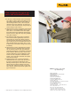
Continuity
One common continuity appli-
cation is checking switches or
breakers for continuity when they
are closed. With power removed
from the switch, place the tester
probes on the two switch con-
tacts. If the switch is working
properly, the tester will illuminate
the continuity LED and sound
the beeper continuously when
the switch is closed. No need to
power the tester on or select a
function. As long as there is no
voltage present, the tester auto-
matically comes on and selects
the continuity function.
GFCI testing
Both the T+ and the T+PRO
have a GFCI test function. After
installing a GFI protected circuit,
say a kitchen outlet branch cir-
cuit for example, apply power to
the circuit by closing the breaker
at the power panel. Go to one
of the kitchen outlets and place
the tester’s black lead into the
ground (not neutral) socket and
the red lead into the hot (small
slot) socket. If the branch circuit
is wired properly, the tester will
immediately illuminate the LEDs
to indicate normal voltage. Next,
press the tester’s GFCI button
and leave tester connected for
seven seconds. While testing, the
dc (+) and dc (-) LEDs will blink
to indicate the GFCI test is active.
If the GFI circuit is operating nor-
mally, the GFCI should trip and
remove power from the circuit.
With no power, the tester’s LEDs
should extinguish. Reset the GFCI
circuit and repeat the test from
the next outlet.
When measuring ac voltage
between phases of a three-
phase circuit, the T+PRO tester
indicates the phase relation-
ship between the two test
leads as well as the voltage.
A typical application is con-
necting a three-phase motor
and testing for proper rotation
direction. Connect the tester’s
leads between two of the phase
conductors. The tester’s display
will indicate a clockwise rota-
tion ( ) when the red test
lead voltage is 120° ahead of the
black lead. You’ll see a counter-
clockwise indicator ( ) when
the phase between the leads is
reversed. Next, move the red test
lead to the third phase conductor
to see its phase relationship to
the other two conductors. Now
you can connect the conductors to
the motor for the desired rotation.
Press the ohms Ω button to
switch the tester to resistance
mode. Now, you can check resis-
tors in motors, fuses, switches,
relays, or other general resis-
tance applications on dead cir-
cuits, up to 9.99 kΩ.
Last but not least, because the
T+PRO can measure down to
10 V with three digits of accu-
racy, it’s a far more accurate tool
for low-voltage lighting applica-
tions. Most standard electrical
testers (solenoid and solid-state)
only measure down to 12 V and
may not be able to see that a
step-down lighting transformer
is only putting out 10.8 volts.
(That’s a 10 % variance from
what the voltage should be.)
Depending upon the set up, the
bulbs may not function properly
(or at all). The farther down the
line you go from the transformer,
the greater the possible voltage
drop—but a standard voltage tes-
ter may still read 12 V, leading
you to believe that everything is
fine.
For more information on indus-
trial and HVAC applications, read
the Fluke application note “HVAC
applications for the Fluke T+ and
T+PRO Electrical Testers.”