
Cut Sheet

Application Note
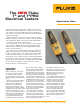
The NEW Fluke
T
+
and T
+
PRO
Electrical Testers
F r o m t h e F l u k e D i g i t a l L i b r a r y @ w w w . f l u k e . c o m / l i b r a r y
The first electrical tester had a simple solenoid that
pulled an indicator attached to a spring across a spe-
cial voltage scale. The higher the voltage applied to
the solenoid, the further the indicator would be pulled
against the spring.
High accuracy is not a big concern when installing
lighting, switches, and other common electrical wiring
and equipment. Often, you just need to differentiate
common voltages from one another.
The problem is, these classic testers are no longer
safe to use by NFPA electrical measurement stan-
dards. Many companies have outright barred them
from the field and floor.
Since the basic measurement need was still there,
Fluke developed two new testers that did what elec-
tricians needed them to do. The new T+ and T+PRO
ac/dc electrical testers are rated to CAT IV 600 V
and CAT III 1000 V and use light, sound, and vibration
to indicate voltage. They also test for continuity and
GFCI and are low impedance. Additionally, the T+PRO
model has a LCD digital readout screen, a rotary
phase indicator, and resistance.
And, on the T+PRO, a digital
readout of either measurement
will appear on the LCD. If the
batteries fail, the LEDs will still
light up, so that the user always
has voltage detection capability.
Both testers measure ac and dc
voltage from 12 to 600 volts (the
T+PRO measures down to 10.2 V
on the LCD). For the residential
electrician, the T+ model covers
all of the basic electrical mea-
surements, from voltage entering
the house at the power panel,
to the output of the transformer
powering the doorbell.
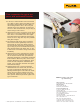
One typical use is checking
a 240 V ac outlet for a dryer or
range for correct wiring. Place
the tester’s probes between the
two hot sockets of the outlet. The
tester will automatically come
Basic voltage
applications
Before starting any test, touch
the two leads of the T+PRO or
T+ together. All of the LEDs
should light up. That means the
tester is working and has battery
power.
These testers have nine LEDs,
each of which indicates a spe-
cific voltage, that illuminate
when the test leads contact
voltage. At the same time, the
testers beep and vibrate strongly
enough that you can feel it when
voltage is detected. For ac volt-
age, the ac LED lights up and the
beeper makes a chirping sound.
For dc voltage, the dc positive
or negative LED lights up and
the beeper makes a steady tone.
on, illuminate the LEDs to indi-
cate 240 V ac, beep, vibrate, and
illuminate the hazardous voltage
LED. Next, check for 120 V ac
between each hot and neutral
socket of the outlet.
For industrial techs, check volt-
age balance between phases—is
it within 2 %—and for voltage
drop across motor contactors
or relays, where voltage drop
should be negligible. Also check
control circuit voltage. To elimi-
nate measurement errors from
ghost or stray voltages, these
testers’ low input impedance
loads the circuit and absorbs any
ghost voltage energy. That gives
you a reliable indication that the
circuit you are testing is truly
dead.