
User's Manual


Table Of Contents
- Models 175, 177, 179 True RMS Multimeters
- Models 175, 177 & 179 True RMS Multimeters
- Contacting Fluke
- "Warning" and "Caution" Statements
- Unsafe Voltage
- Test Lead Alert
- Battery Saver ("Sleep Mode")
- Terminals
- Rotary Switch Positions
- Display
- MIN MAX AVG Recording Mode
- Display HOLD and AutoHOLD Modes
- YELLOW Button
- Display Backlight (Model 177 and 179 Only)
- Manual Ranging and Autoranging
- Power-Up Options
- Making Basic Measurements
- Using the Bar Graph
- Cleaning
- Testing the Fuses
- Replacing the Battery and Fuses
- Specifications
Models 175, 177 & 179
Users Manual
8
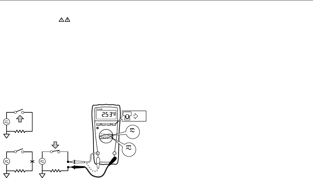
Measuring AC or DC Current
Warning
To avoid personal injury or damage to the Meter:
• Never attempt to make an in-circuit current measure-
ment when the open-circuit potential to earth is
> 1000 V.
• Check the Meter's fuses before testing. (See “Testing
the Fuses”.)
• Use the proper terminals, switch position, and range
for your measurement.
• Never place the probes in parallel with a circuit or
component when the leads are plugged into the
current terminals.
Turn power OFF, break circuit, insert Meter in series, turn power
on.
CAT
CAT
+
+
RANGEHOLD
MIN MAX
mA
A
DC
AIK08F.EPS
Understanding AC Zero Input Behavior of True RMS Meters
Unlike averaging meters, which can accurately measure only pure
sinewaves, True RMS meters accurately measure distorted
waveforms. Calculating True RMS converters require a certain
level of input voltage to make a measurement. This is why AC
voltage and current ranges are specified from 5% of range to
100% of range. Non-zero digits that are displayed on a True RMS
meter when the test leads are open or are shorted are normal.
They do not affect the specified AC accuracy above 5% of range.
Unspecified input levels on the lowest ranges are:
• AC voltage: below 5% of 600 mV AC, or 30 mV AC
• AC current: below 5% of 60 mA AC, or 3 mA AC